Line printer hammer banks

a line printer and hammer bank technology, applied in the field of line printers, can solve the problems of carbon and carbonless printing, the difficulty of manufacturing the shuttle mechanism and the hammer bank, the added complexity and cost of manufacture, and the inability to service or replace the hammer bank in the field, so as to achieve the effect of efficient and easy manufacturing and cost reduction

Active Publication Date: 2014-04-24
PRINTRONIX LLC
View PDF0 Cites 0 Cited by
  • Summary
  • Abstract
  • Description
  • Claims
  • Application Information

AI Technical Summary

Benefits of technology

[0009]In accordance with embodiments of the present invention, hammer banks for line impact printers are provided that are both efficient and reliable, yet substantially easier and lower in cost to manufacture and service than prior art devices.

Problems solved by technology

Additionally, because the printing involves impact or mechanical pressure, these printers can also produce carbon and carbonless copies.
While these and other prior art line printer hammer banks can provide satisfactory print quality and speeds, they are not without some drawbacks.
For example, prior art hammer banks typically comprise a machined or die cast base part that is relatively expensive to make, and which is substantially integrated in the shuttle mechanism, which makes both the shuttle mechanism and the hammer bank more difficult and expensive to manufacture and to remove for servicing or replacement of the hammer bank in the field.
Additionally, conventional hammer banks typically incorporate relatively complex, dual-pole-piece magnetics for the control of each hammer, which adds to their complexity and cost of manufacture.
Accordingly, there is a long felt but as yet unsatisfied need in the relevant industry for hammer bank designs that are both efficient and reliable, yet which are easier and lower in cost to manufacture and service.

Method used


Image

  • Line printer hammer banks
  • Line printer hammer banks
  • Line printer hammer banks

Examples


Embodiment Construction

[0020]In accordance with the present disclosure, embodiments of hammer banks for line printers are provided, together with methods for making them, that are both efficient and reliable, yet substantially easier and lower in cost to manufacture and service than prior art devices.

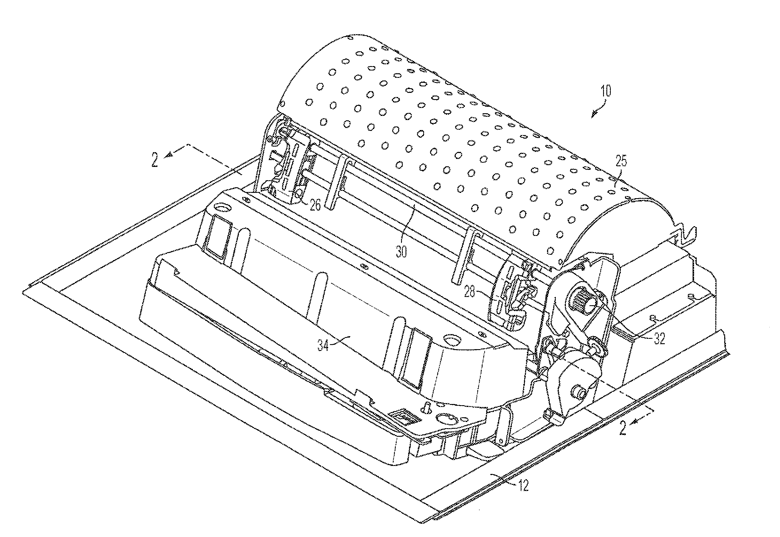
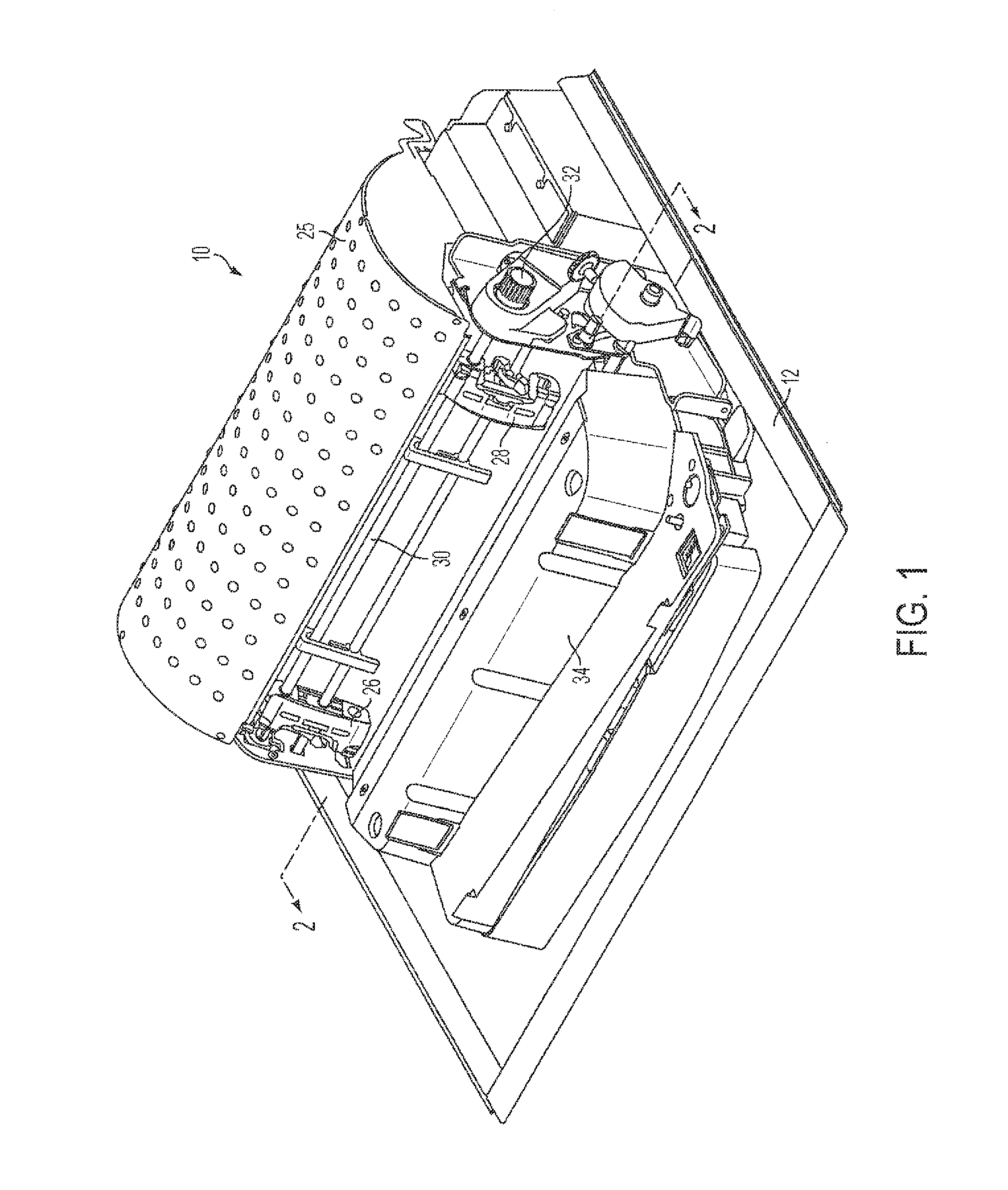
[0021]FIG. 1 is a perspective view of an example line matrix impact printer 10 within which embodiments of the present invention can be advantageously employed. As illustrated in FIG. 1, the printer 10 can be mounted on a stand or a base, or incorporated in a cabinet. In the particular embodiment illustrated, the printer 10 is shown supported within a base frame 12. The base frame 12 supports all of the various components of the printer 10, including a cartridge ribbon system (not illustrated), which comprises an “endless” or Mobius strip of ink ribbon housed inside a cartridge that is fed across the print medium by a motor that creates tension on the ribbon by use of gears on one side and a tension spring on...


PUM

PropertyMeasurementUnit
thicknessaaaaaaaaaa
magnetic forceaaaaaaaaaa
magnetic fluxaaaaaaaaaa

Abstract

In one embodiment, a hammer bank for a line printer includes a back plate having a front surface, a back surface and a uniform thickness between the front and back surfaces. At least one hammer is disposed in front of the back plate. The at least one hammer is spring-biased for forward movement and away from the back plate and is releasably retained against such forward movement by a magnetic force acting rearwardly thereon. An elongated pole piece that is associated with the at least one hammer extends forwardly from the front surface of the back plate and is selectively operable to interrupt the magnetic force acting thereon.

Description

RELATED APPLICATIONS[0001]This application is a continuation of U.S. patent application Ser. No. 13 / 654,095, filed Oct. 17, 2012, now U.S. Pat. No. ______, issued ______.BACKGROUND[0002]1. Technical Field[0003]This invention relates to line printers in general, and more particularly, to hammer banks for line printers that are both easier and lower in cost to manufacture and service.[0004]2. Related Art[0005]Line impact matrix printers, or line printers, produce letters and graphics in the form of a matrix of dots by employing a “shuttle” mechanism that runs back and forth in a horizontal direction over a page of a print medium, such as single sheet or continuous form paper, coupled with movement of the page perpendicular to that of the shuttle. An inked “ribbon” is typically interposed between the shuttle and the page. The shuttle comprises a “hammer bank,” i.e., an inline row of cantilevered, magnetically retracted hammer printing tips respectively disposed on the ends of elongated...

Claims


Application Information

Patent Timeline
Patent Type & Authority Applications(United States)
IPC IPC(8): B41J9/04
CPCB41J9/04Y10T29/49826
Inventor GEMMELL, JOHN W.SHARMA, ROHITCONCEPCION, JR., RUDY
Owner PRINTRONIX LLC
Why Eureka
Try Eureka