
Method and automated system for control of oil well production and modular skid for use in said method

an automated system and oil well technology, applied in the direction of gas/liquid distribution and storage, water supply installation, fluid removal, etc., can solve the problems of liquid level using a measuring tape, reducing the validity of extrapolation procedures, and challenging filling the control tank, so as to improve the measurement of well production and reduce errors , the effect of reducing the overall size of surface installations and reducing the testing tim

Inactive Publication Date: 2014-04-10
YPF TECHA
View PDF5 Cites 15 Cited by
  • Summary
  • Abstract
  • Description
  • Claims
  • Application Information

AI Technical Summary

Benefits of technology

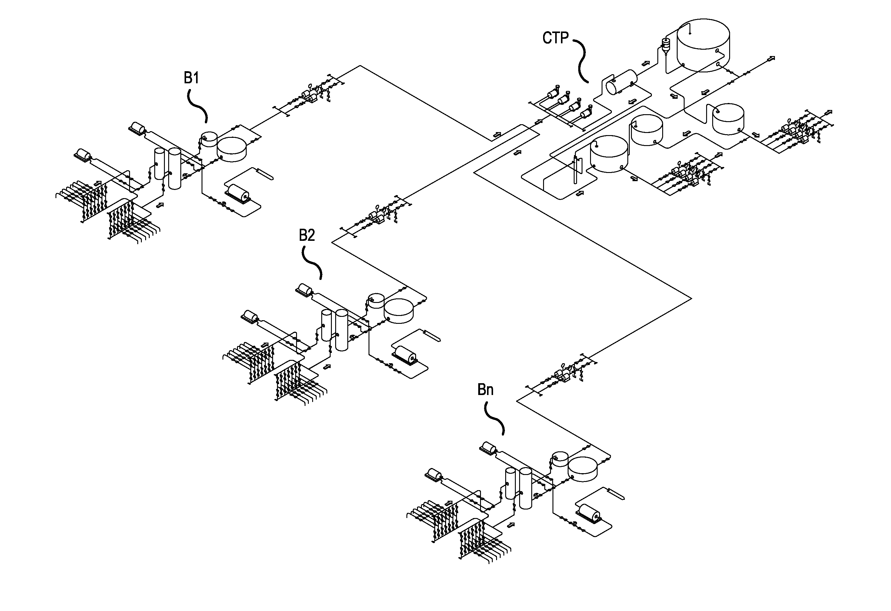
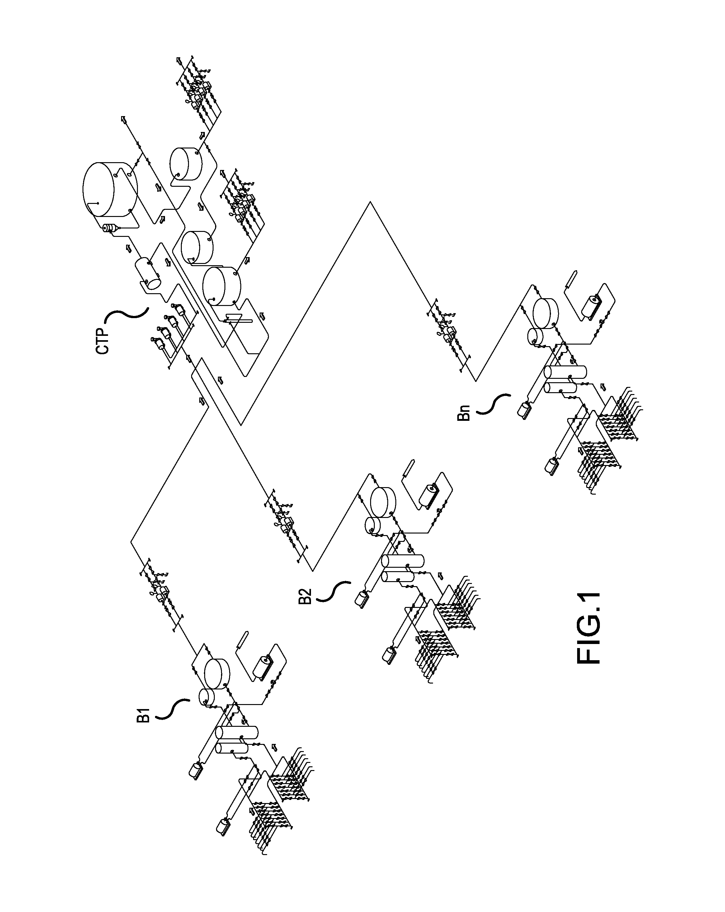
The present invention provides a method for optimizing oil production from wells by continuously measuring gross production and water cut. This is achieved by building a reliable production allocation system that improves measurement accuracy and understanding of oil field behavior. The method allows for faster control of well production, reduces the time spent in control process, and ensures real-time measurement with reduced error and measurement times. It also facilitates automation of process control and reduces operating expenditures and capital expenditures. Additionally, the invention provides a safety system to ensure a safe process and avoid environment damage.

Problems solved by technology

However, wells in marginal fields generally have production rates with a wide variability and a high water cut, by which in some cases, filling the control tank can be technically challenging, either with the volume produced over a 24 hour or an even longer time period in the case of a low production rate, or with the short time required to fill the tank in the case of a very high production rate.
In case no level sensors are available in the tank, the measurement is dependent on a manual time measurement, which further decreases the validity of the extrapolation procedure.
Yet another source of error is the measuring of the liquid level using a measuring tape.
This is due not only to the error associated with a manual measuring, but also to the fact that the measuring action must be performed with a moving fluid inside the control tank, a situation explicitly counter-indicated in the API MPMS Standards.
In addition, there is a further source of error derived from the control tank calibration chart and its use, given that a manual interpolation must often be performed.
Finally, a single tank measurement is not enough to determine gross production.
Production temperatures of approximately 30 to 40° C. imply a high oil thermal expansion coefficient, which can result in a volumetric error greater than 1%.
While the main advantage of said system relies on the automation of the control procedure, there is limited capability for real-time measurement and monitoring of real-time variables, such as instantaneous and average well production, water cut, fluid density, temperature, etc.
A further disadvantage of said system is the use of a storage tank.

Method used


Image

  • Method and automated system for control of oil well production and modular skid for use in said method
  • Method and automated system for control of oil well production and modular skid for use in said method
  • Method and automated system for control of oil well production and modular skid for use in said method

Examples


Embodiment Construction

[0069]The invention will be described in detail below with reference to the figures.

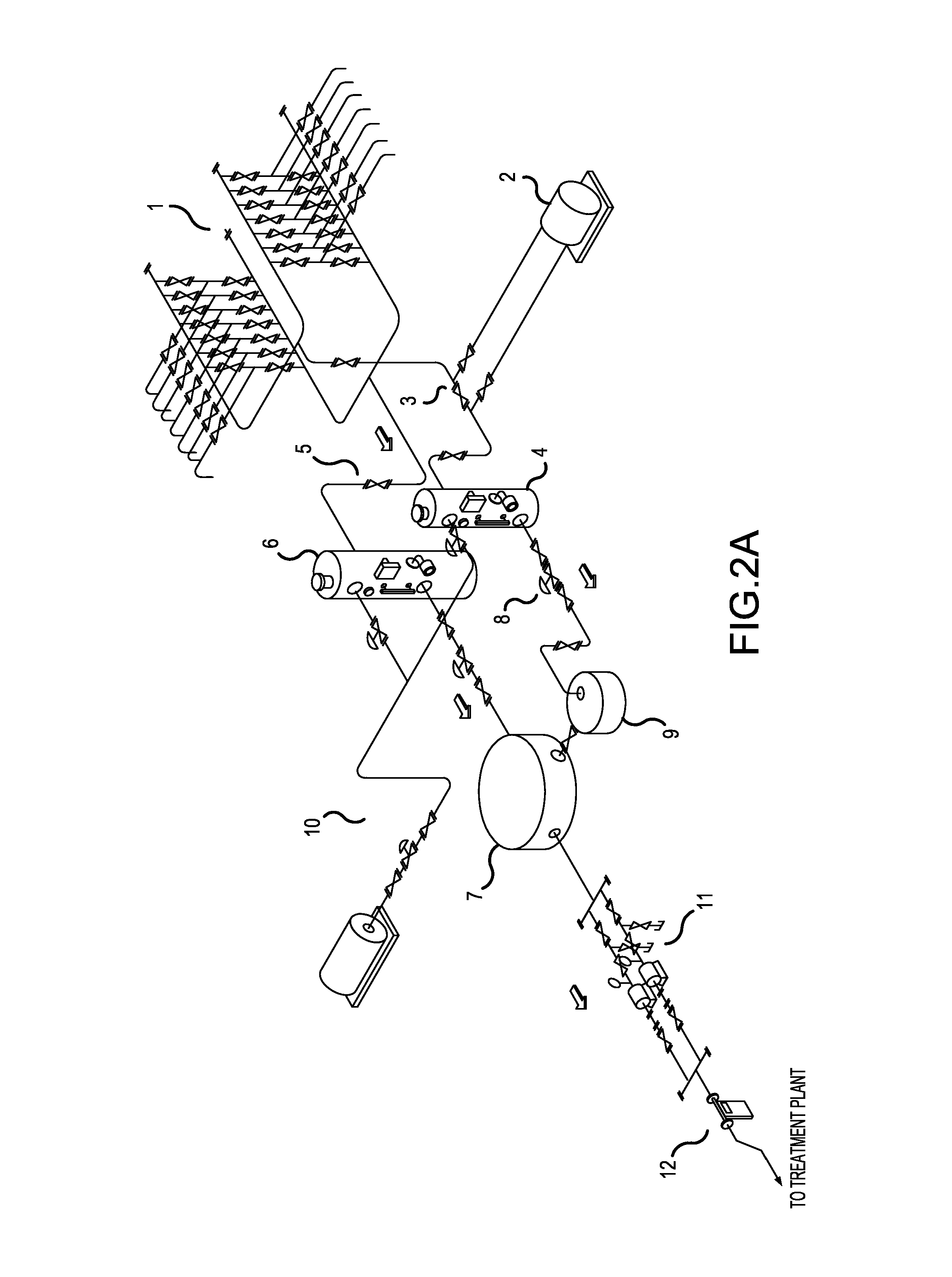
[0070]FIG. 2a shows a flowchart of a traditional battery in an oil production process. A manifold 1 is used for guiding a stream of produced fluid from a well, by means of one or more of various pump systems, like rod pumps, electrical submersible pumps (ESP), etc. Said manifold is connected to a control line 3, comprising a heater 2, a two-phase control separator 4, a control valve 8 and a control tank 9. The general installation line 5 comprises a two-phase general separator 6, a general tank 7, connected through a plurality of pumps 11 to a line leading to a treatment plant. The gross liquid production stored in the general tank 7 is pumped to the treatment plant by means of said pump assembly 11. The liquid is measured by a measuring bridge consisting of a mass flow meter and a water cut analyzer. Both the general separator 6 and the control separator 4 have an output for a gas line 10 which is s...


PUM


Abstract

Automated measurement and oil well production control may be achieved by using a vertical separator, the discharge flow of which is continuously adjusted by setting the opening of a control valve, determined by the liquid level inside the separator. The automation of the control method allows real-time measurements of several process variables as well as reduced measurement times and also works as a safety layer for a production process. The control method is independent of well production and is therefore suited to controlling marginal wells.

Description

CROSS-REFERENCE TO RELATED APPLICATIONS[0001]This application claims priority of U.S. Provisional Application No. 61 / 710,507 filed on Oct. 5, 2012 under 35 U.S.C. §119(e), the entire contents of which are hereby incorporated by reference.FIELD OF THE INVENTION[0002]This invention relates to an automated well production measurement and control system also working as a safety layer for the production process and to a modular skid for its implementation.BACKGROUND OF THE INVENTION[0003]Oil production is the process by which a reservoir fluid is transported to the surface to be separated into oil, gas and water. If necessary, the obtained oil and gas will be treated and conditioned for sale or transport from the field to a petroleum refinery. The so called “upstream operations” consist of the exploration, development and production of crude oil, water and natural gas.[0004]The production process is carried out in a surface installation. This installation includes wells, manifolds, pipel...

Claims


Application Information

Patent Timeline
IPC IPC(8): E21B43/12
CPCE21B43/12E21B43/34Y10T137/7759Y10T137/0368
Inventor ROMERO MAIMONE, REYNALDO MARTINLAGO ESPINA, CARLOS ALBERTOALONSO PENIZOTO, CLAUDIO ALBERTO
Owner YPF TECHA
Learn More