
Foundation System and Method of Use for Decreasing the Effect of Wind and Flood Damage

a foundation system and flood damage technology, applied in the field of foundation systems, can solve the problems of high winds, long-term flooding, permanent damage to the house structure, and the subject pier foundation to damage or even catastrophic destruction, and achieve the effect of enhancing the connection and strengthening the connection

Inactive Publication Date: 2014-04-10
BENET RUSSELL E
View PDF9 Cites 1 Cited by
  • Summary
  • Abstract
  • Description
  • Claims
  • Application Information

AI Technical Summary

Benefits of technology

This patent is about a foundation system that strengthens the connection between a home's foundation and the pier(s) that support it. It includes multiple security boots that improve the connection between the pier and the sill plates of the home. Additionally, it describes a method for quickly raising the house to prevent damage to the foundation caused by a surge of water from a heavy snowstorm. Overall, this foundation system increases the stability and security of the home's foundation.

Problems solved by technology

Unfortunately, there are severe weather conditions in many coastal regions that may still subject pier foundations to damage or even catastrophic destruction.
For instance, hurricanes often strike along coastal areas and bring very high winds, storm surges, and long-term flooding.
Strong winds that are not able to pass around or through a house's foundation may cause permanent damage to the house structure.
Similarly, a strong storm surge may be higher than the foundation sill plate and cause instant damage to the foundation or, at least, cause flooding in the house.
When storm elements, such as wind and storm surge, bear against the pilings and foundation, “notched piling failure” occurs.
The connection point of the foundation breaks away from the piling and catastrophic structural collapse occurs.

Method used


Image

  • Foundation System and Method of Use for Decreasing the Effect of Wind and Flood Damage
  • Foundation System and Method of Use for Decreasing the Effect of Wind and Flood Damage
  • Foundation System and Method of Use for Decreasing the Effect of Wind and Flood Damage

Examples


Embodiment Construction

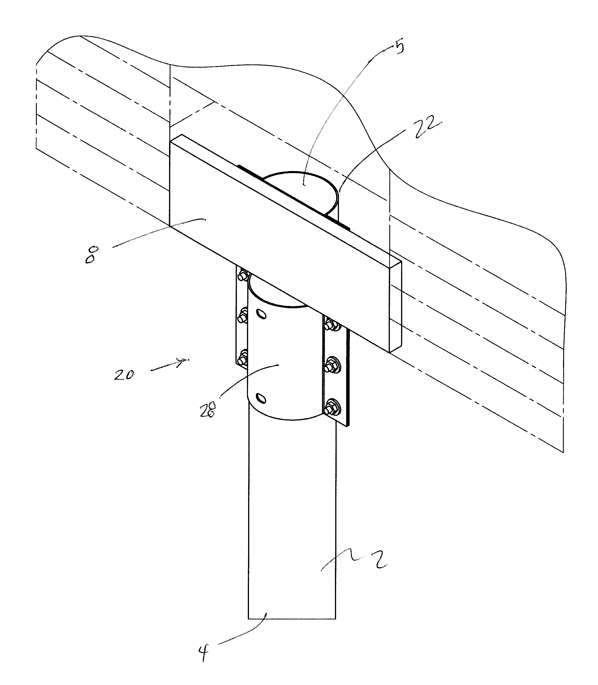
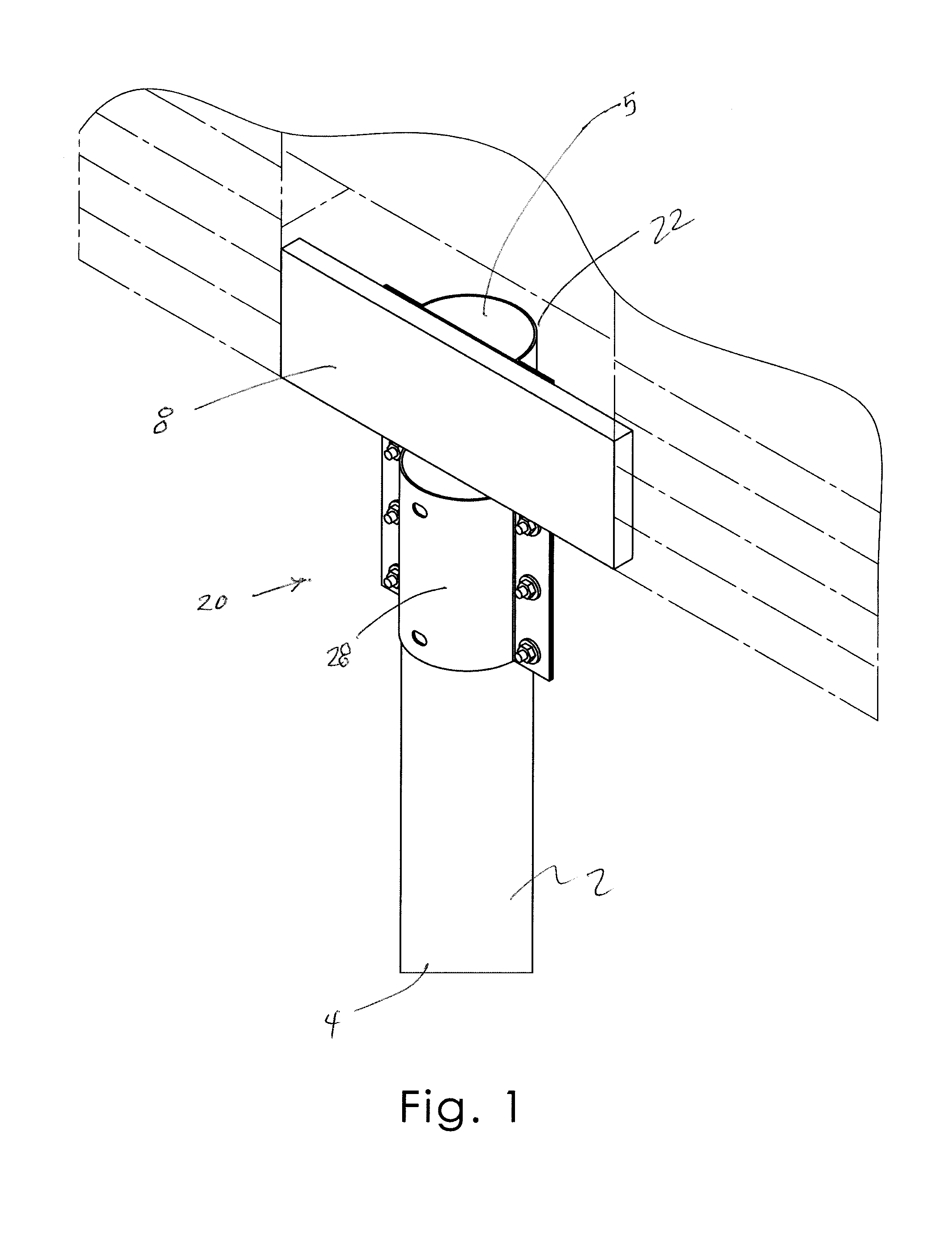
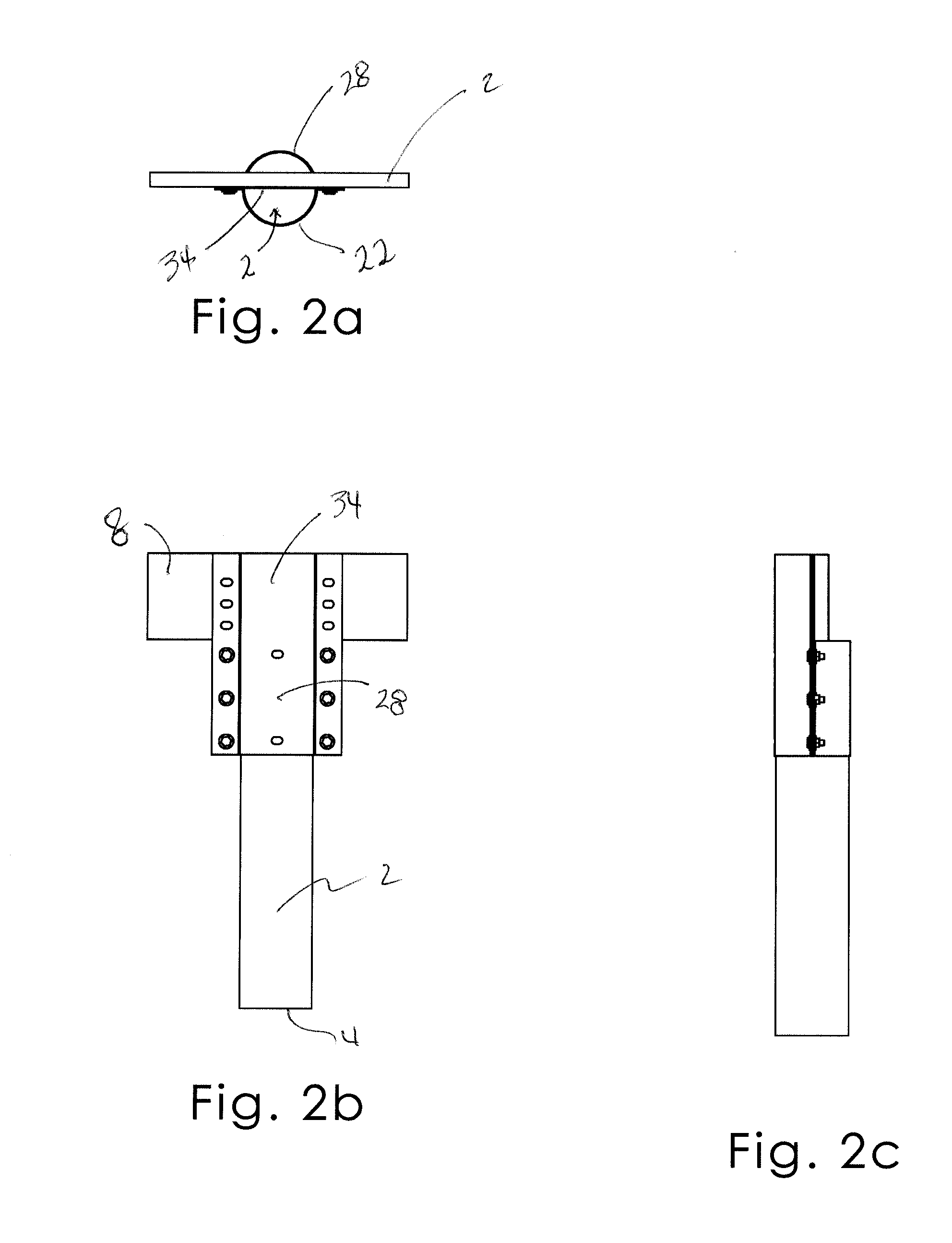
[0037]A foundation system and a method of use so as to decrease the effects of wind, flood, and storm surge will now be described with reference with to FIGS. 1 to 16 of the accompanying drawings. The foundation system 10 includes security boot 20, a pier sleeve 40, and a lifting device 50.

[0038]The present invention is intended to be used to secure structures that are built on a pier system, such as homes built near the ocean, wetlands, or other area where a traditional foundation is not feasible. Piers 2 used for this type of construction may be generally cylindrical posts that are at a lower end 4 embedded in the ground and at an upper end 5 include a notched area 6 suitable for receiving a sill plate 8 of a building's foundation (FIG. 3 and FIG. 1). A sill plate 8 is typically a horizontally situated board for forming an exterior and base support for the foundation.

[0039]The security boot 20 provides a structure that may be received over the upper end 5 of a pier 2. The security...


PUM


Abstract

A foundation system includes a security boot selectively coupled to a pier having a notched upper end. The security boot includes first, second, and third portions complementary to the pier upper end. The security boot third portion includes a configuration complementary to a foundation sill plate and is selectively coupled thereto. The foundation system includes a sleeve configured to be received on a pier, the security boot configured to surround the sleeve and be slidable therealong. The system includes at least one lifting device having a base member and rod configured to engage the sill plate and is movable between a retracted configuration not urging movement of the sill plate and an extended configuration urging the sill plate upwardly. In a method of using the foundation system, the lifting devices may be actuated to lift an entire foundation upwardly from the piers, the security sliding upwardly along an associated sleeve.

Description

[0001]REFERENCE TO RELATED PATENT APPLICATION[0002]This application is related to U.S. Design patent application Ser. No. 29 / 414,037, filed Feb. 23, 2012, and titled “Foundation Support,” now pending.BACKGROUND OF THE INVENTION[0003]This invention relates generally to foundation systems and, more particularly, to a foundation strengthening system and method of use for decreasing the catastrophic damage to building foundations caused by wind, floods, and storm surges associated with hurricanes.[0004]Foundations for homes and buildings in coastal regions are often built on a piering system. Long cylindrical piers—sometimes called pilings or posts—are drilled into the ground and extend upwardly. Then large beams are situated horizontally across the piers in a notched area at upper ends of the piers so as to support a home or other building atop the piers. A pier and beam foundation has the advantage of allowing wind and water to pass beneath the house under normal conditions.[0005]Unfo...

Claims


Application Information

Patent Timeline
Patent Type & Authority Applications(United States)
IPC IPC(8): E04H9/14E02D27/32E02D35/00
CPCE02D27/32E04H9/14E04H9/145Y02A30/00Y02A50/00
Inventor BENET, RUSSELL E.
Owner BENET RUSSELL E
Learn More