Eureka AIR delivers breakthrough ideas for toughest innovation challenges, trusted by R&D personnel around the world.

Apparatus and methods for large particle ash separation from flue gas using screens having semi-elliptical cylinder surfaces

a technology of semi-elliptical cylinders and screens, which is applied in the direction of filtration separation, lighting and heating apparatus, and separation processes, etc., can solve the problems of nitrous oxide being considered a pollutant to the atmosphere, clogging up the catalytic reactor, damage to the screens, etc., and achieves the effect of reducing the overall pressure drop over the screen, reducing the flue gas velocity at the screen surface, and increasing the surface area of the screen

Active Publication Date: 2014-04-03
INTEGRATED GLOBAL SERVICES
View PDF1 Cites 21 Cited by
  • Summary
  • Abstract
  • Description
  • Claims
  • Application Information

AI Technical Summary

Benefits of technology

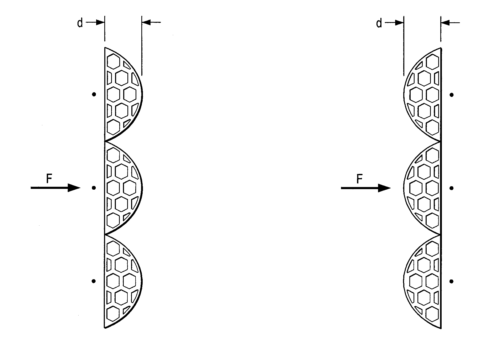
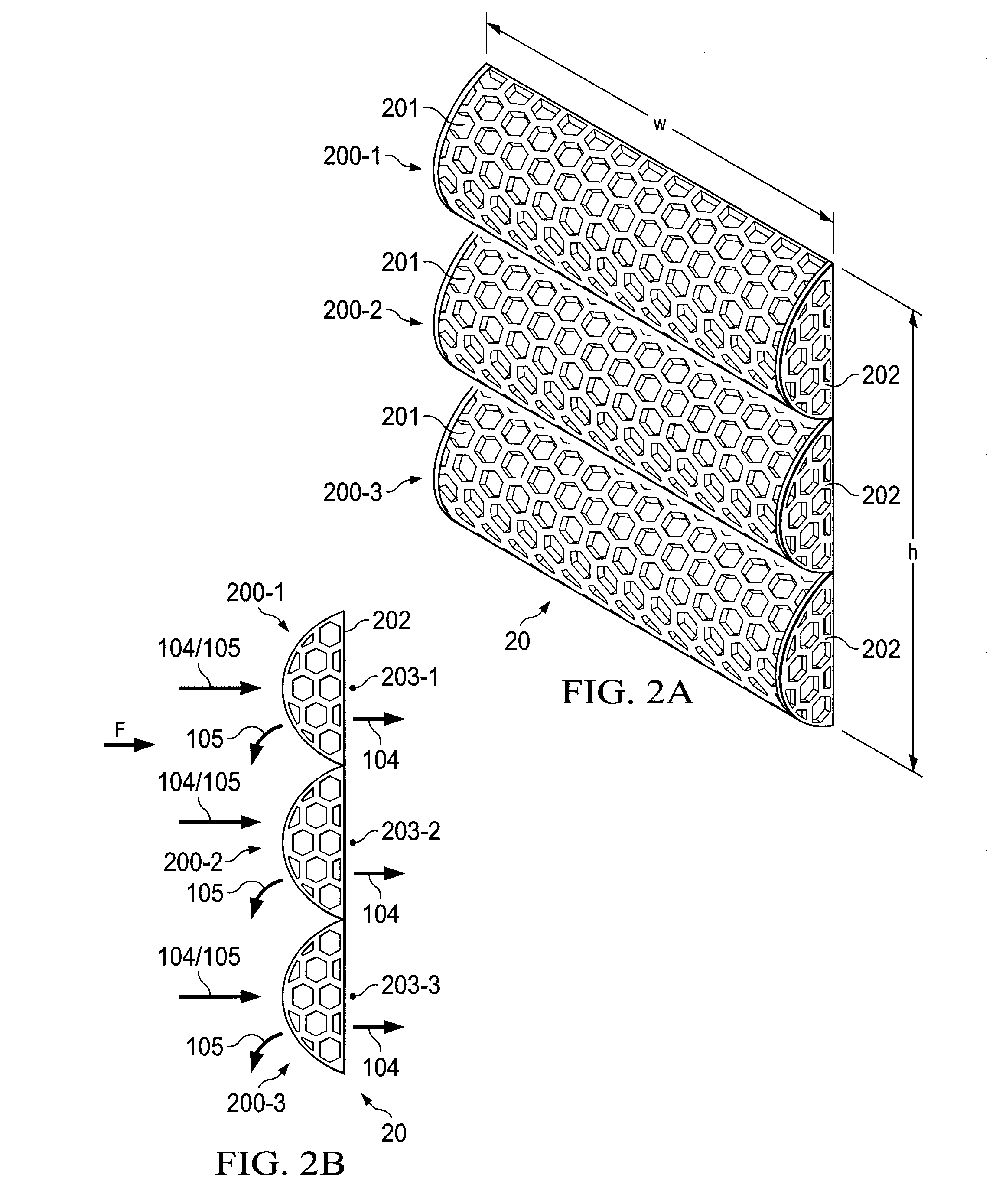
The invention is a screen with special surfaces that can catch ash particles from flue gas. These surfaces have holes for the gas to flow through, but the shape of the screen ensures that the ash particles cannot pass through. By using a screen with semi-elliptical cylinder surfaces, the gas can flow smoothly through the screen and the surfaces are maximized for catching ash particles. This results in improved efficiency and a longer lifespan for the screen material.

Problems solved by technology

This nitrous oxide is considered a pollutant to the atmosphere.
LPA particles are larger than the catalyst opening and therefore clogs up the catalytic reactor.
In practice, these screens experience blockage in certain areas of the pleated arrangement, which creates high velocity zones that cause damage to the screens.
As a result, these pleated screens have to be replaced frequently or perform inefficiently and increase pressure drop in the system.
It should also be noted that channels through which flue gas flows are large and, at least for this reason, screens used in these channels to separate ash from flue gas are also large and can be relatively costly.
The length of the duct makes this system relatively expensive.
The pleated screen design and baffle arrangement utilizing gravimetric forces do not economically remove large particle ash.
Another problem in the art is that the ash particles in the flue gas erode structural duct members and separation screens.
High flue gas velocities combined with hard ash particles will lead to significant metal wastage of this equipment.
In summary, existing systems and methods for screening ash particles from flue gas are associated with high operating costs and high capital expenditure.

Method used


Image

  • Apparatus and methods for large particle ash separation from flue gas using screens having semi-elliptical cylinder surfaces
  • Apparatus and methods for large particle ash separation from flue gas using screens having semi-elliptical cylinder surfaces
  • Apparatus and methods for large particle ash separation from flue gas using screens having semi-elliptical cylinder surfaces

Examples


Embodiment Construction

[0020]FIG. 5A shows prior art system 50 for separating large ash particles from flue gas. Ash particles, as discussed herein are large and may be about 1-2 centimeters in diameter. System 50 represents a typical coal fired power plant boiler arrangement. At boiler 500, coal is mixed with air (from preheater 505) and burned. The burning coal causes an increase in temperature in boiler 500 such that water injected into boiler 500 is vaporized to steam. As mentioned above, the burning coal produces ash particles 105, which flows with hot flue gas 104 through duct 501. Duct 501 leads to screen 506. Screen 506 has holes having a diameter such that flue gas is allowed to pass through screen 506. However, at least some ash particles are too big to pass through the holes of screen 506. Because these ash particles are too big to pass through the holes of screen 506, they accumulate in hopper 502. Flue gas passes through screen 506 and enters duct 503. Duct 503 channels flue gas 104 to Select...


PUM

PropertyMeasurementUnit
Pressure dropaaaaaaaaaa
Areaaaaaaaaaaa
Velocityaaaaaaaaaa

Abstract

Apparatus for separating ash particles from a flue gas. The apparatus includes a screen that has a plurality of semi-elliptical cylinder surfaces. The semi-elliptical cylinder surfaces having holes through which said flue gas flows and through which the ash particles will not pass. The screen has a single layer for performing the separation in a manner such that the ash particles fall away from the screen and collect outside of the screen. A method of reducing velocity of a flue gas passing through screening apparatus for separating flue gas from ash particles. The method includes replacing a first screen of the screening apparatus with a second screen that has a plurality of semi-elliptical cylinder surfaces.

Description

CROSS-REFERENCE TO RELATED APPLICATIONS[0001]This Application is related to U.S. patent application Ser. No. (Fulbright Docket Number IGSP.D0001US), entitled ______, not yet filed, the disclosures of which are hereby incorporated herein by reference.TECHNICAL FIELD[0002]The present disclosure is related to the control of particulate emissions from industrial plants such as coal fired plants. More specifically, the present disclosure is related to the separation of large particle ash from flue gas utilizing screens.BACKGROUND[0003]Coal is a primary source of energy today and is commonly used as fuel to produce electricity. A byproduct of producing electricity in a coal combustion process is nitrous oxide (NOx), which is emitted with a flue gas from coal burning electrical generating plants. This nitrous oxide is considered a pollutant to the atmosphere. Catalytic reactors are used to address this type of pollution by reducing the nitrous oxide concentration in the flue gas. Ash is an...

Claims


Application Information

Patent Timeline
IPC IPC(8): B01D46/00
CPCB01D46/103B01D39/10B01D2258/0283B01D2275/20B01D2275/206F23J3/04Y10T29/4973
Inventor BUZANOWSKI, MARK A.CRAWFORD, RICHARD B.KING, JAKEHALL, IAIN STUART
Owner INTEGRATED GLOBAL SERVICES
Why Eureka
Eureka Blog
Learn More