Vehicle and control method for vehicle

a technology for controlling methods and vehicles, applied in the direction of electric propulsion mounting, transportation and packaging, tractors, etc., can solve the problem of not being able to appropriately respond to a driver's driving force request, and achieve the effect of suppressing a variation in the driving force of the vehicl

Active Publication Date: 2014-03-27
TOYOTA JIDOSHA KK
View PDF3 Cites 5 Cited by
  • Summary
  • Abstract
  • Description
  • Claims
  • Application Information

AI Technical Summary

Benefits of technology

[0009]The invention provides a vehicle that is able to suppress a variation in vehicle driving force when a drive system of the vehicle is restarted while the vehicle is coasting, and a control method for the vehicle.
[0022]According to the first and second aspects, it is determined whether to shift into the second state where generation of driving force based on the operation amount of the accelerator pedal is allowed on the basis of a behavior of the accelerator pedal while the vehicle is travelling in the first state where driving force from the drive device is suppressed. Specifically, while the vehicle is travelling in the first state, a shift into the second state is prohibited until the operation amount of the accelerator pedal once becomes lower than the predetermined value. Thus, a shift into the second state in a state where depression of the accelerator pedal is not loosened even once is suppressed while the vehicle is travelling in the first state. Thus, according to these aspects, when the drive system of the vehicle is restarted while the vehicle is coasting, it is possible to suppress a variation in vehicle driving force, which is not intended by the driver.

Problems solved by technology

However, there is a case where, even when the throttle opening degree is lower than or equal to the predetermined opening degree but when the throttle opening degree does not decrease after a restart of the drive system, the drive system should not be restarted.
Therefore, it is not possible to appropriately respond to a driver's driving force request.

Method used


Image

  • Vehicle and control method for vehicle
  • Vehicle and control method for vehicle
  • Vehicle and control method for vehicle

Examples


first embodiment

[0035]FIG. 1 is an overall block diagram of a vehicle according to the invention. As shown in FIG. 1, the vehicle 100 includes a drive device 105, an electrical storage device 110, a system main relay (hereinafter, referred to as “SMR”) 115, an accelerator pedal 170 and an electronic control unit (hereinafter, referred to as “ECU”) 300.

[0036]The drive device 105 includes a power control unit (hereinafter, referred to as “PCU”) 120, motor generators 130, 135, a power transmission gear 140, a drive wheel 150 and an engine 160. The PCU 120 includes a converter 121, inverters 122, 123, and capacitors C1, C2.

[0037]The electrical storage device 110 is a rechargeable direct-current power supply, and is, for example, formed of a secondary battery, such as a lithium ion battery, nickel metal hydride battery and a lead-acid battery. The electrical storage device 110 is electrically connected to the PCU 120 of the drive device 105 via power lines PL1, NL, and supplies electric power for genera...

second embodiment

[0077]FIG. 5 is a timing chart that shows an example of operation of the vehicle 100 when the vehicle system enters the ready-off state while the vehicle is travelling according to the As shown in FIG. 5, it is assumed that, at time t11, a shift from the ready-on state to the ready-off state has occurred while the vehicle is travelling.

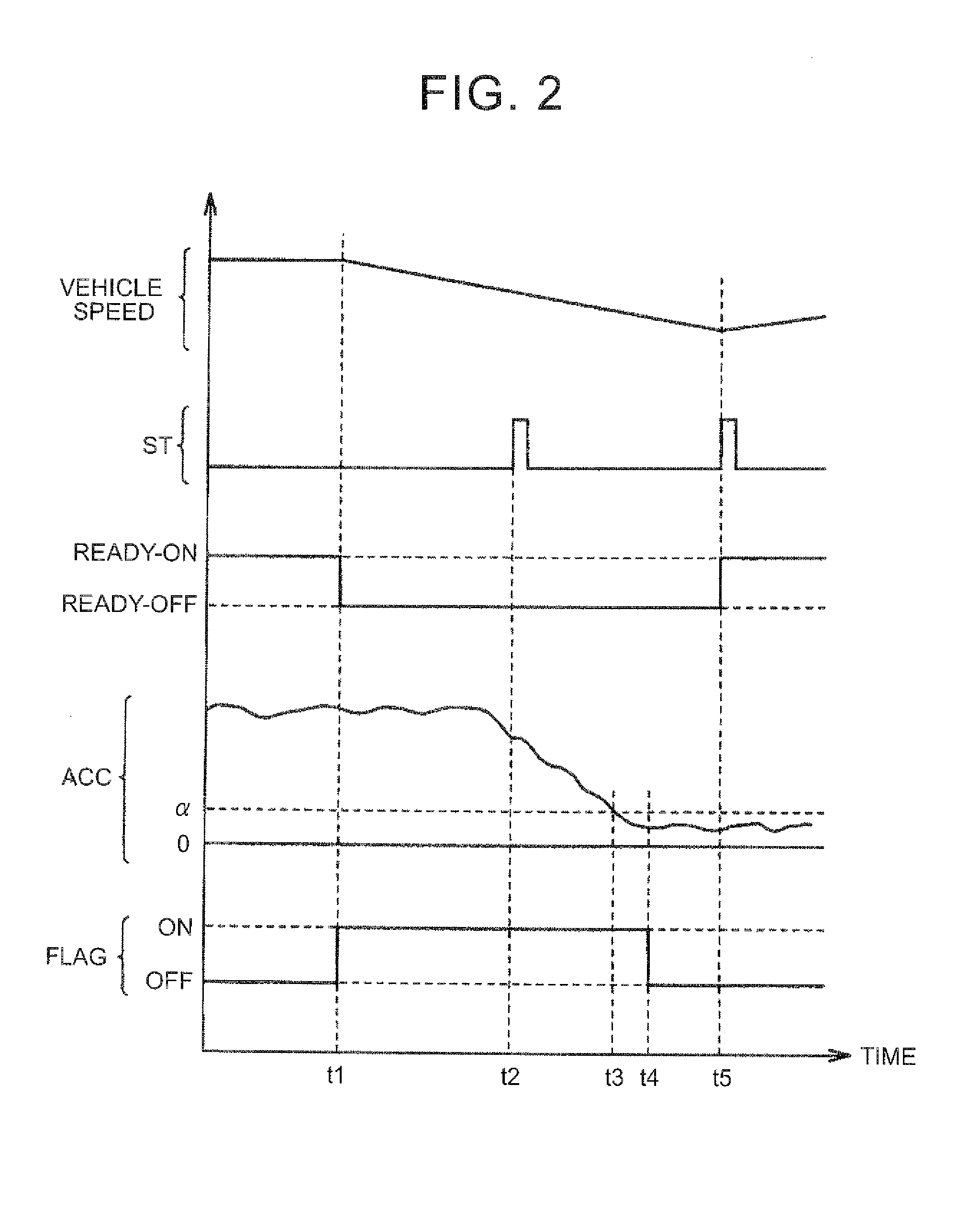
[0078]In the second embodiment, when it has been detected that the accelerator operation amount ACC is higher than or equal to the predetermined value α (nonzero) and a fluctuation range of the accelerator operation amount ACC is smaller than a predetermined range β, the accelerator high operation amount flag is set in the on state (time t12). That is, when the accelerator pedal 170 has been depressed to a certain amount and it is determined that there is no likelihood of return of the accelerator pedal 170 on the basis of a fluctuation amount of the accelerator operation amount ACC, the accelerator high operation amount flag is set to the on state, ...

third embodiment

[0093]In a third embodiment, when it has been detected that the accelerator operation amount ACC is higher than or equal to the predetermined value α (nonzero) and the fluctuation range of the accelerator operation amount ACC is smaller than the predetermined range β, the accelerator high operation amount flag is set to the on state. The on state of the accelerator high operation amount flag is kept and a shift (return) into the ready-on state is prohibited until the accelerator operation amount ACC once becomes lower than a predetermined value (which may be the same value as the above-described predetermined value α or may be different from the above-described predetermined value α).

[0094]The overall configuration of the vehicle according to the third embodiment is the same as the configuration of the vehicle 100 according to the first embodiment shown in FIG. 1.

[0095]FIG. 8 is a flowchart that illustrates a process that is executed by the ECU 300 when the vehicle system enters the...


PUM


Abstract

A vehicle includes an accelerator pedal, a drive device and an electronic control unit (ECU). The drive device generates driving force for driving a wheel on the basis of an operation amount of the accelerator pedal. The ECU, while the vehicle is travelling in a ready-off state, prohibits a shift into a ready-on state until the operation amount of the accelerator pedal once becomes lower than a predetermined value.

Description

INCORPORATION BY REFERENCE[0001]The disclosure of Japanese Patent Application No. 2012-214349 filed on Sep. 27, 2012 including the specification, drawings and abstract is incorporated herein by reference in its entirety.BACKGROUND OF THE INVENTION[0002]1. Field of the Invention[0003]The invention relates to a vehicle and a control method for a vehicle and, more particularly, to a vehicle including a drive device that generates driving force for driving a wheel on the basis of an operation amount of an accelerator pedal, and a control method for the vehicle.[0004]2. Description of Related Art[0005]If the power of a drive system of a vehicle turns off from any cause, such as driver's erroneous operation of a start / stop switch of the vehicle during travelling, generation of driving force by a drive device, such as an engine and a drive motor, is stopped, and the vehicle coasts. In this case, in order to cause the vehicle to appropriately travel thereafter, it may be desired to allow a ...

Claims


Application Information

Patent Timeline
Patent Type & Authority Applications(United States)
IPC IPC(8): B60K28/10B60W10/06B60W20/00B60L50/16
CPCB60K28/10B60W10/06B60W20/40B60W20/00B60W2030/1809B60W2540/10B60W2540/103Y02T10/40
Inventor TANAKA, NOBUYUKIAMANO, MASAYAUCHIDA, KENJIHAYAKAWA, YUKIHAYASAKA, GO
Owner TOYOTA JIDOSHA KK
Why Eureka
Try Eureka