
Laminated ceramic capacitor

Active Publication Date: 2014-02-13
MURATA MFG CO LTD
View PDF3 Cites 12 Cited by
  • Summary
  • Abstract
  • Description
  • Claims
  • Application Information

AI Technical Summary

Benefits of technology

The invention relates to a laminated ceramic capacitor with improved resistance to moisture. This is achieved by reducing the average grain size in the dielectric ceramic layers, which reduces residual stress and improves resistance to corrosive solutions. However, a challenge is to maintain sinterability while reducing the average grain size in the inner layer section, which can result in defects and decrease in dielectric constant. To address this challenge, the average grain size is reduced in the outer layer section to ensure moisture resistance, while increased in the inner layer section to ensure sinterability. Additionally, the patent discusses how the addition of Mn can improve the chemical stability of the dielectric ceramic layers and prevent peeling of the interfaces between the internal electrodes and the dielectric ceramic.

Problems solved by technology

When the average grain size is increased in the outer layer sections, peeling defects between the grains are likely to occur in a moisture-resistance loading test and the like.
The defects in the moisture-resistance loading test are believed to be caused by ingress of a plating solution or moisture through erosion of defective external electrodes and ceramic grain boundaries by the plating solution or moisture.
It is considered in this case that larger grain sizes produce more residual stress in the ceramic, make the stress more likely to be released when grain boundaries are eroded, and make cracks more likely caused, as compared with smaller grain sizes.

Method used


Image

  • Laminated ceramic capacitor
  • Laminated ceramic capacitor
  • Laminated ceramic capacitor

Examples


example 1

[0029]Respective powders of CaCO3, SrCO3, BaCO3, TiO2, and ZrO2 with a purity of 99% or more were prepared as materials for a main constituent constituting the dielectric ceramic. These materials were weighed in predetermined amounts, then subjected to wet mixing in a ball mill, and thereafter, dried and crushed. This powder was subjected to calcination at 900° C. to 1300° C. in the atmosphere, and then crushed to obtain a main constituent powder including a perovskite-type compound containing Ca and Zr. It is to be noted that the method for producing the main constituent may be a solid-phase method, a hydrothermal method, etc. without particular limitation, and the materials may be also carbonates, oxides, hydroxides, etc. without particular limitation.

[0030]Next, powders of SiO2, MnCO3, and an oxide of M (where M is an element selected from alkali metals, alkali-earth metals, rare earths, and V) were prepared as additive materials. The additives were weighed in predetermined amoun...


PUM

PropertyMeasurementUnit
Grain sizeaaaaaaaaaa
Substance countaaaaaaaaaa
Grain sizeaaaaaaaaaa

Abstract

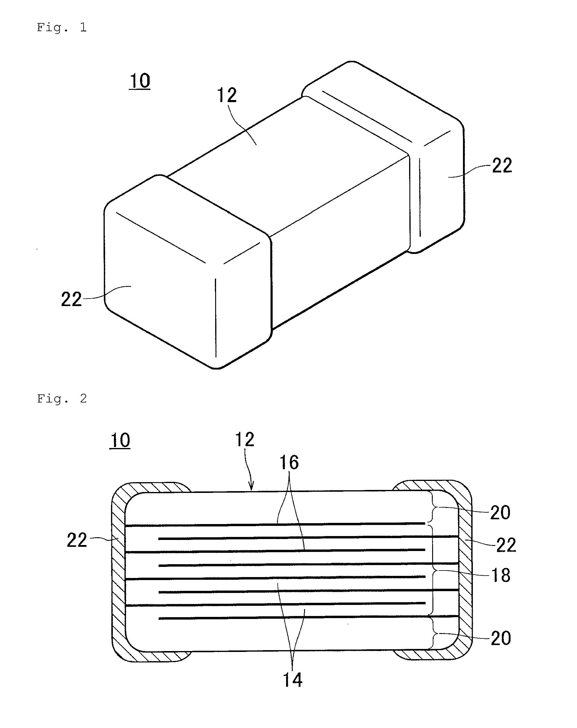
laminated ceramic capacitor which has favorable moisture resistance includes an inner layer section that has dielectric ceramic layers and internal electrodes stacked alternately, and outer layer sections formed outside the inner layer section. The dielectric ceramic layers have a perovskite-type compound including a main constituent containing Ca and Zr, and an additive containing Si and Mn. The average grain size in the dielectric ceramic layers constituting the outer layer sections is smaller than the average grain size in the dielectric ceramic layers constituting the inner layer section. The Si / Mn molar ratio in the dielectric ceramic near the interfaces between the internal electrodes and the dielectric ceramic layers is ≦15.

Description

BACKGROUND OF THE INVENTION[0001]1. Field of the Invention[0002]This invention relates to a laminated ceramic capacitor, and more particularly, relates to a laminated ceramic capacitor using a dielectric ceramic containing, for example, Ca and Zr.[0003]2. Description of the Related Art[0004]Laminated ceramic capacitors have a stacked structure of dielectric ceramic layers and internal electrodes. As a dielectric ceramic material for use in the ceramic layers of these laminated ceramic capacitors, for example, a non-reduced dielectric ceramic material is disclosed which contains a main constituent represented by [(CaXSr1-X)O]m[(TiYZr1-Y)O2] where the values of X, Y, and m respectively fall within the range of: 0≦X≦1, 0≦Y≦0.10, and 0.75≦m≦1.04, and containing, as accessory constituents, 0.2 to 5 mol % of Mn oxide in terms of MnO, 0.1 to 10 mol % of Al oxide in terms of Al2O3, and 0.5 to 15 mol % of constituent represented by [(BaZCa1-Z)O]VSiO2 where Z and V respectively fall within th...

Claims


Application Information

Patent Timeline
IPC IPC(8): H01G4/30
CPCH01G4/30B32B18/00C04B35/486C04B35/49C04B2235/3201C04B2235/3203C04B2235/3208C04B2235/3213C04B2235/3215C04B2235/3217C04B2235/3224C04B2235/3225C04B2235/3239C04B2235/3262C04B2235/3418C04B2235/6584C04B2235/768C04B2235/785C04B2235/786C04B2237/348C04B2237/588C04B2237/704H01G4/1227H01G4/1245
Inventor HIRATA, TOMOTAKANISHIMURA, HITOSHIISOTA, SHINYAOGURA, TAKETSUGUNAITO, MASAHIRO
Owner MURATA MFG CO LTD
Learn More