
Refrigerant scroll compressor for motor vehicle air conditioning systems

a technology of refrigerant scroll compressor and air conditioning system, which is applied in the direction of machines/engines, rotary/oscillating piston pump components, liquid fuel engines, etc., can solve the problems of only being able to control oil return and intermediate pressure, and the relative short axial installation length of the compressor, so as to improve the redundancy of lubricating the scroll, increase the functional reliability of the compressor, and stable sealing function

Inactive Publication Date: 2014-02-06
HANON SYST
View PDF7 Cites 6 Cited by
  • Summary
  • Abstract
  • Description
  • Claims
  • Application Information

AI Technical Summary

Benefits of technology

The invention is a refrigerant scroll compressor for motor vehicle air-conditioning systems, which ensures stable oil return and well-controlled sealing force for sealing the fixed scroll to the orbiting scroll. The patent describes an intermediate pressure duct that can be designed cost-effectively and can be formed on the bottom of the orbiting scroll. This duct allows for stable oil return and management of the sealing force between the scrolls, resulting in improved functional reliability of the compressor. By using this design, the invention overcomes the disadvantage of inaccurate and complicated control and management of the intermediate pressure by a mixture of refrigerant oil and refrigerant gas. The invention provides a stable intermediate pressure in the intermediate pressure chamber and ensures the axial sealing force during the compression of the refrigerant gas between the scrolls. These technical effects improve the performance and reliability of the scroll compressor for air-conditioning systems.

Problems solved by technology

Scroll compressors moreover operate radially to the inside, which results in a relatively short axial installation length for the compressor.
A known problem with refrigerant scroll compressors consists of the fact that the oil return must be designed for process safety and at the same time must be able to develop a sufficient sealing force with reference to the orbiting scroll by controlling the intermediate pressure.
This design from the prior art has the disadvantage, however, that the oil return and the intermediate pressure can only be poorly controlled.

Method used


Image

  • Refrigerant scroll compressor for motor vehicle air conditioning systems
  • Refrigerant scroll compressor for motor vehicle air conditioning systems
  • Refrigerant scroll compressor for motor vehicle air conditioning systems

Examples


Embodiment Construction

[0023]The following detailed description and appended drawings describe and illustrate various exemplary embodiments of the invention. The description and drawings serve to enable one skilled in the art to make and use the invention, and are not intended to limit the scope of the invention in any manner.

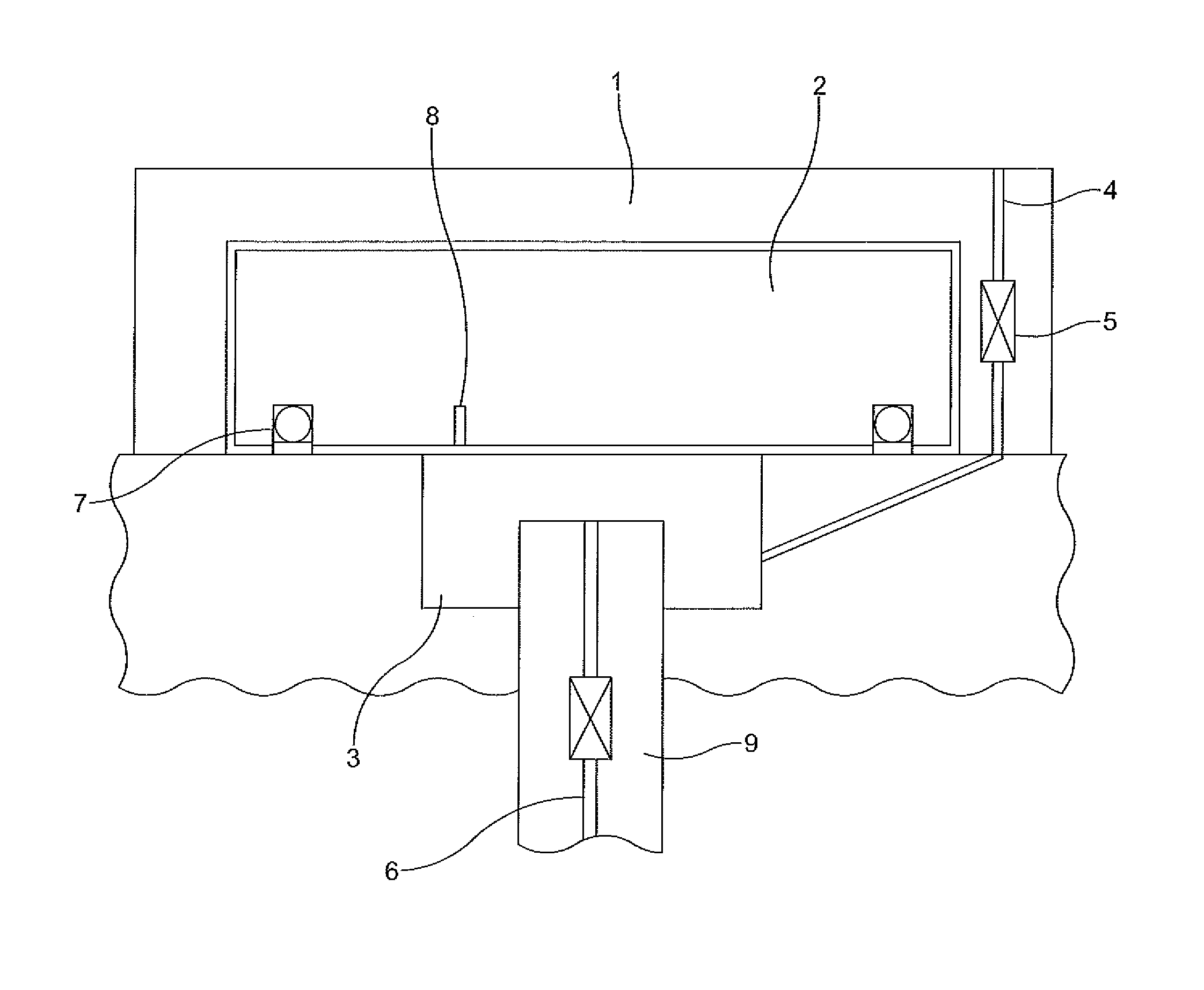
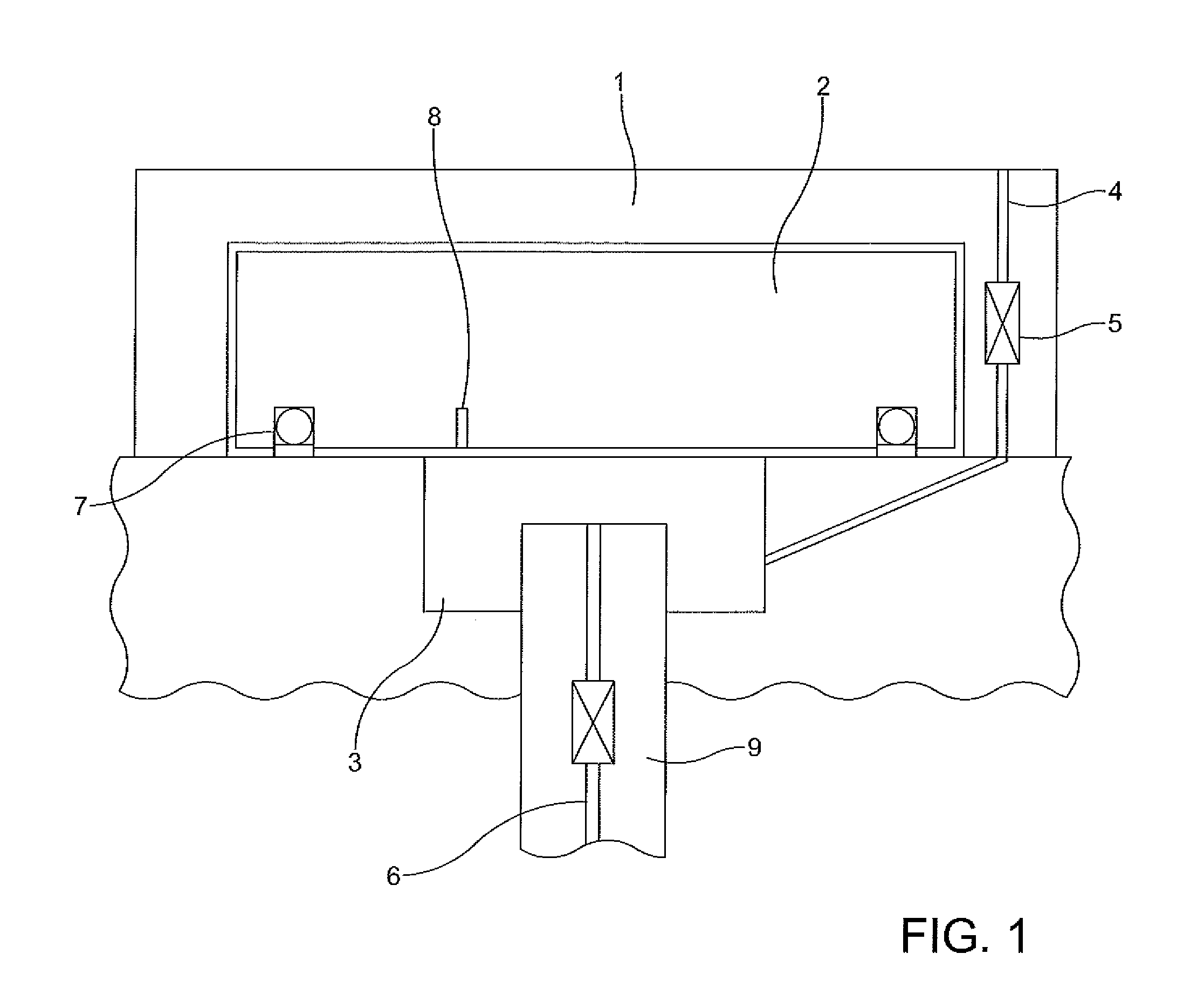
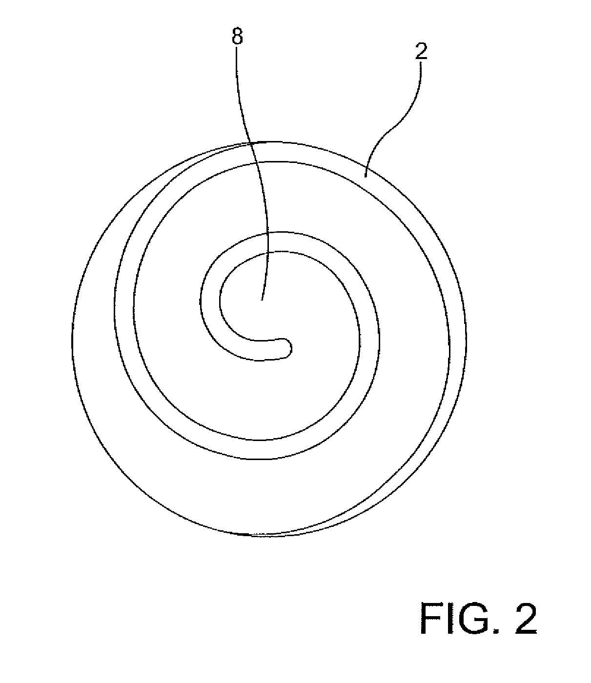
[0024]FIG. 1 shows a highly schematic cross-section of a refrigerant scroll compressor. For this purpose, and according to the functional principle, an orbiting scroll 2 is located in a fixed scroll 1. The orbiting scroll 2 moves in an oscillating manner in the fixed scroll 1 such that between the scrolls 1, 2, cavities are formed which decrease radially from the outside to the inside, in which the refrigerant gas is compressed from the outside to the inside and the compressed refrigerant gas inside is finally discharged axially into the high-pressure chamber. FIG. 1 illustrates an intermediate pressure chamber 3 below the scrolls 1, 2, in which the refrigerant gas exists at an inter...


PUM


Abstract

A refrigerant scroll compressor for a motor vehicle air conditioning system having a fixed scroll, an orbiting scroll engaging with the fixed scroll, wherein the fixed scroll and the orbiting scroll cooperate to compress a refrigerant gas. An intermediate pressure chamber is disposed adjacent the orbiting scroll, an oil return duct provides fluid communication between the intermediate pressure chamber and a high pressure area of the refrigerant scroll compressor, and at least one intermediate pressure duct is formed in one of the orbiting scroll and fixed scroll and is in fluid communication with the intermediate pressure chamber.

Description

CROSS-REFERENCE TO RELATED APPLICATION[0001]This application claims priority to German Non-Provisional Patent Application Serial No. DE 10 2012 104 045.1 filed May 9, 2012, hereby incorporated herein by reference in its entirety.FIELD OF THE INVENTION[0002]The invention relates to a refrigerant scroll compressor for vehicle air-conditioning systems and in this context particularly a design with efficient oil recirculation within the refrigerant circuit while controlling the intermediate pressure level optimally.BACKGROUND OF THE INVENTION[0003]The use of refrigerant scroll compressors in motor vehicle air-conditioning systems is highly desirable, since this type of compressor has a robust structural design and can also be produced and used cost-effectively. Scroll compressors moreover operate radially to the inside, which results in a relatively short axial installation length for the compressor. An electrical refrigerant compressor can thus be designed without requiring any additio...

Claims


Application Information

Patent Timeline
Patent Type & Authority Applications(United States)
IPC IPC(8): F04C18/02
CPCF04C18/0215F04C27/005F04C18/0261F04C27/002F04C27/003F04C29/026
Inventor SCHNEIDER, PETERGUNTERMANN, BERNDKLOTTEN, THOMASHECKT, ROMANWOELK, PETER MICHAEL
Owner HANON SYST
Learn More