
Bio-electrochemical system for treating wastewater

a bio-electrochemical and wastewater technology, applied in water treatment multi-stage treatment, separation processes, radioactive contaminants, etc., can solve the problems of high water treatment cost, high retention time and large foot-print required, and current anaerobic digestion methods are typically ineffective for treating water. , to achieve the effect of improving biogas quality, simple and robust system, and increasing wastewater treatment ra

Active Publication Date: 2013-11-14
CAMBRIAN INNOVATION
View PDF9 Cites 31 Cited by
  • Summary
  • Abstract
  • Description
  • Claims
  • Application Information

AI Technical Summary

Benefits of technology

The present invention introduces a system and method for efficiently treating wastewater and biogases using novel electrogenic microbes. The invention improves wastewater treatment rates and biogas quality while reducing operating costs. The technology increases the biological removal of unwanted compounds from gas, particularly hydrogen sulfide, for cleaner combustion. Overall, the invention provides a simple and effective solution for wastewater and biogas treatment.

Problems solved by technology

Unfortunately AD has certain disadvantages including: (1) relatively high retention times and large foot-print required; (2) high concentrations of CO2 in biogas; (3) a requirement for pH control (addition of caustic); (4) the complex association of microbial partners required for an AD system to function optimally results in the system being sensitive to changes in temperature, pH and influent organics and; (5) elevated levels of hydrogen sulfide (H2S) in the biogas.
Current anaerobic digestion methods are typically ineffective for treating water to levels low enough for environmental release.
The cumulative effect of these drawbacks, keep the cost of wastewater treatment high, which, thereby affects applications for a range of industries and municipalities.
One of the most important problems associated with AD is elevated levels of hydrogen sulfide (H2S) in the biogas.
H2S is odorous, very corrosive to internal combustion engines, and considered an air pollutant, and thus must be removed (or scrubbed) from biogas prior to combustion.
However, the chemical storage, metering, and control equipment all add to the cost of a scrubber.
The chemicals are hazardous, and the amounts required to treat H2S are quite high, so the cost of operating the scrubber can quickly add up.
The downside of such biological filtration methods is that is can be slower than chemical scrubbing and often requires upkeep including addition of nutrients and the influx of significant amounts of air into the system.

Method used


Image

  • Bio-electrochemical system for treating wastewater
  • Bio-electrochemical system for treating wastewater
  • Bio-electrochemical system for treating wastewater

Examples


example 1

Bio-Trickling Filter Based Bio-Electrochemical System

[0092]The bio-trickling filter BES system converts a basic biotrickling filter into a bio-electrochemical system. In traditional bio-trickling filters, a sour gas, or any gas that needs to be cleaned, is passed upwards through a solid matrix such as volcanic rock, on which bacteria can grow. Liquid is re-circulated to provide nutrients and to remove liquid reaction products. Usually, in the case of H2S removal, this likely is very acidic, and results in water that must be reacted with a base such as lime.

[0093]In the system shown in FIG. 8 (A=Anodic H2S Oxidation; B=Electrical connection between anode and cathode; C=Porous Electrically Insulating Layer; D=Cathode: CO2 Reduction; E=Recirculation Pump), the solid substrate for growth is replaced by an electrically conductive substrate such as graphite granules or stainless steel wires (A) and (D). In the first design, we separate two chambers with a space or porous electrically insu...

example 2

Alternative Bio-Trickling Filter Based Bio-Electrochemical System

[0094]An alternative to the design presented above is shown in FIG. 9 (A=Anodic Compartment (gas / liquid phase); B=Electrical connection between anode and cathode; C=Cathodic Compartment (liquid phase); D=Recirculation Pump; E=Baffle for collection of cathodic gas generation), which utilizes the entire trickling filter as an anode compartment (A). In this case, the media can be a conductive solid matrix such as graphite granules or stainless steel wires, or any other conductive substrate. H2S and other gas species are oxidized at the anode and liquid flowing over the substrate trickles the reaction products into the cathode chamber (C). Depending on the reaction products, cathodic reduction in the liquid phase will likely evolve gas, such as hydrogen, which can be collected via a baffle (E) and used as a value-added product or combined with the cleaned biogas to generate a higher value stream. The baffle is optional and...

example 3

Combined Anaerobic Digestion and H2S Filter Based on Bio-Electrochemical System

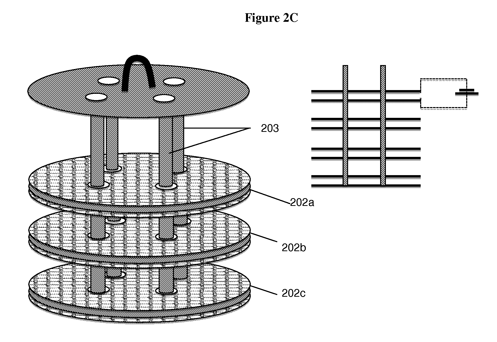
[0095]In the BES system architecture shown in FIG. 10 (A=Anaerobic Digester; B=Electrodes, in which gas phase is anode and liquid phase is cathode), the H2S scrubbing technology described above is coupled with an anaerobic digester. An anode oxidizes hydrogen sulfide in the gases while a cathode reduces CO2 and other elements within the liquid portion of the stream or influent. A voltage can be applied between anode and cathode to optimize rates of oxidation and reduction by the plurality of methanogenic and electrogenic microbes on the electrodes. The result is biogas or natural gas which is sweeter (e.g. lower in hydrogen sulfide) and more abundant in methane versus CO2 than otherwise would be. The electrodes can be any shape or material including, but not limited to flat graphite or stainless steel discs, or graphite granules or any matrix media that is conductive. The electrodes provide support for ba...


PUM

PropertyMeasurementUnit
Electrical conductoraaaaaaaaaa
Electric potential / voltageaaaaaaaaaa

Abstract

The invention relates to bio-electrochemical systems for treating wastewater, and sour gas produced by anaerobic digestion of organic material. The invention further relates to novel anode / cathode pairing schemes, and electric and hydraulic architectures for use in bio-electrochemical systems.

Description

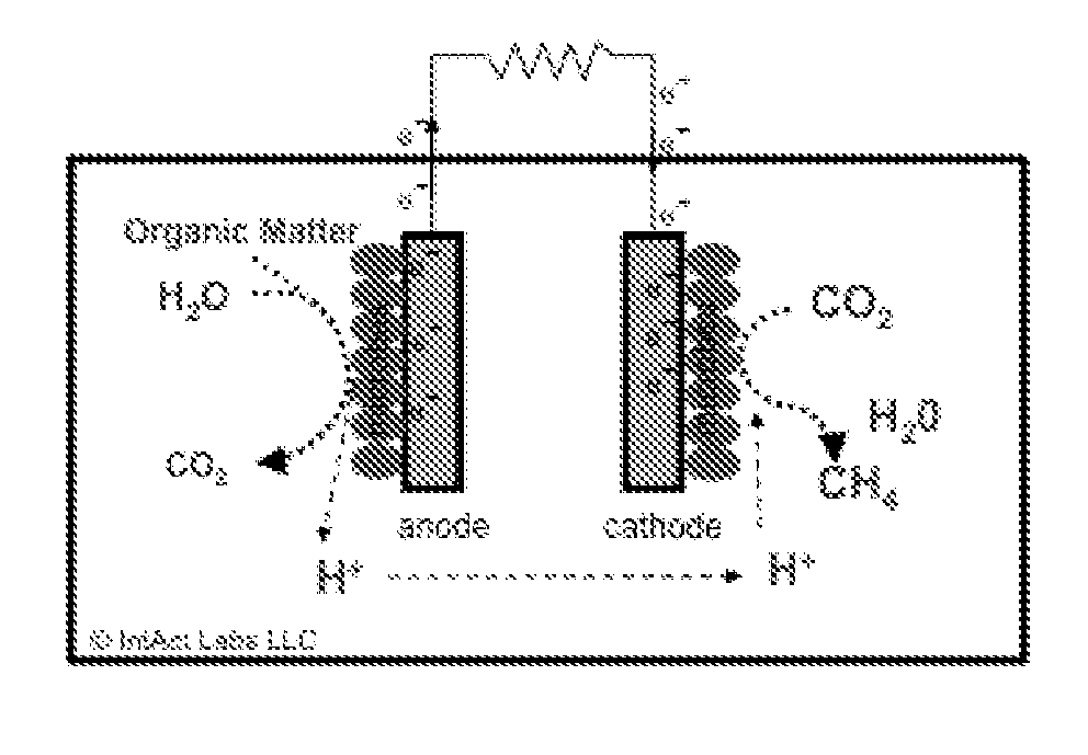
REFERENCE TO RELATED APPLICATIONS[0001]This patent application claims the benefit of U.S. Provisional Application Ser. No. 61 / 366,271, filed Jul. 21, 2010, and U.S. Provisional Application Ser. No. 61 / 394,576, filed Oct. 19, 2010. The contents of each of these applications are herein incorporated by reference in their entireties.TECHNICAL FIELD[0002]The invention generally relates to bio-electrochemical systems for treating water, wastewater, gases, and other biodegradable matter, and generating value-added products from such matter.BACKGROUND OF THE INVENTION[0003]The treatment and monitoring of water is a critical societal need. Approximately three percent (3%) of all electricity produced in the United States is consumed by wastewater treatment infrastructure. Of the electricity produced, approximately one and one-half percent (1.5%) is used in the actual treatment of wastewater. Anaerobic digestion (AD) can be used to treat more concentrated wastewater streams while generating bi...

Claims


Application Information

Patent Timeline
IPC IPC(8): C02F3/00
CPCC02F3/005C02F1/283C02F1/46109C02F1/46114C02F3/1273C02F3/2826C02F3/345C02F2001/46133C02F2001/46157C02F2101/006C02F2103/002C02F2103/005C02F2201/4611C02F2201/46115C02F2201/46135C02F2301/08C02F2303/10Y02E50/30Y02W10/10Y02W10/30Y02W10/37
Inventor SILVER, MATTHEWBUCK, JUSTINKIELY, PATRICKGUZMAN, JUAN J.
Owner CAMBRIAN INNOVATION
Learn More