State space feedback controller in the digital domain for an MRI gradient coil power supply

a feedback controller and state space technology, applied in the direction of magnetic measurement, instruments, measurement devices, etc., can solve the problems of severe deviation and reproducibility, and achieve the effects of increasing bandwidth, cost-effectiveness, and high disturbance suppression

Active Publication Date: 2013-10-31
KONINKLIJKE PHILIPS ELECTRONICS NV
View PDF4 Cites 16 Cited by
  • Summary
  • Abstract
  • Description
  • Claims
  • Application Information

AI Technical Summary

Benefits of technology

The patent is about a method and system for controlling the operation of an MRI gradient magnet system using a digital amplifier system. The system uses a control method that is highly accurate, cost-effective, and can adapt to varying system parameters. This results in a better reproducibility of the output current, leading to better image quality of the MRI system. The approach allows the use of standard digital components, reducing the overall cost of the system.

Problems solved by technology

Due to the above mentioned accuracy requirements of the current pulses for operating the gradient magnet system, known gradient amplifier systems are controlled more or less analogously because a digital control inherently suffers from digital discretization noise and certain digitization effects.
It has revealed that especially the limited resolution of the A / D converters and of the PWM modulators, as well as the limited processing speed of the digital controllers can cause severe deviations and reproducibility problems when generating a desired gradient magnet current.

Method used


Image

  • State space feedback controller in the digital domain for an MRI gradient coil power supply
  • State space feedback controller in the digital domain for an MRI gradient coil power supply
  • State space feedback controller in the digital domain for an MRI gradient coil power supply

Examples


Embodiment Construction

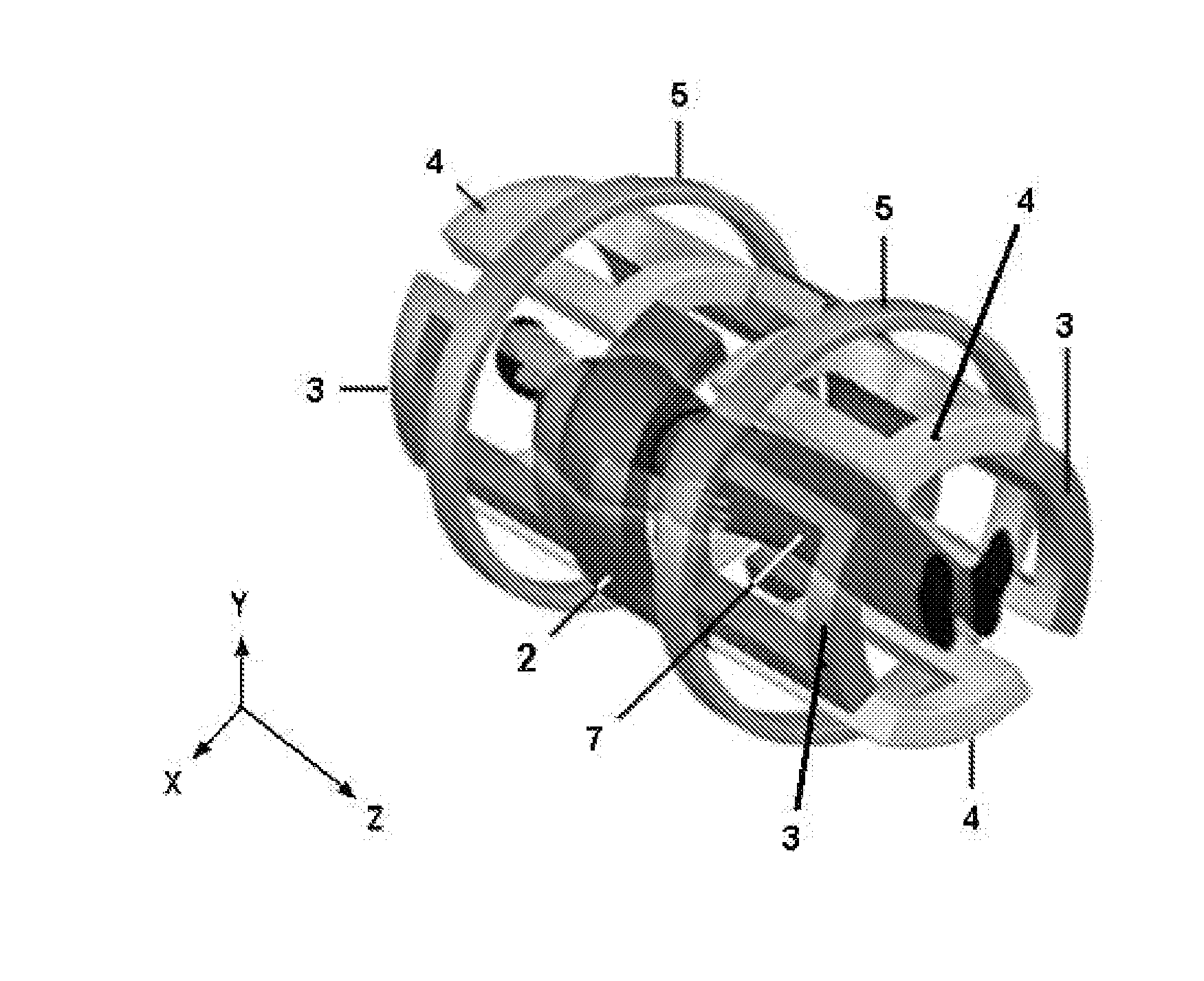
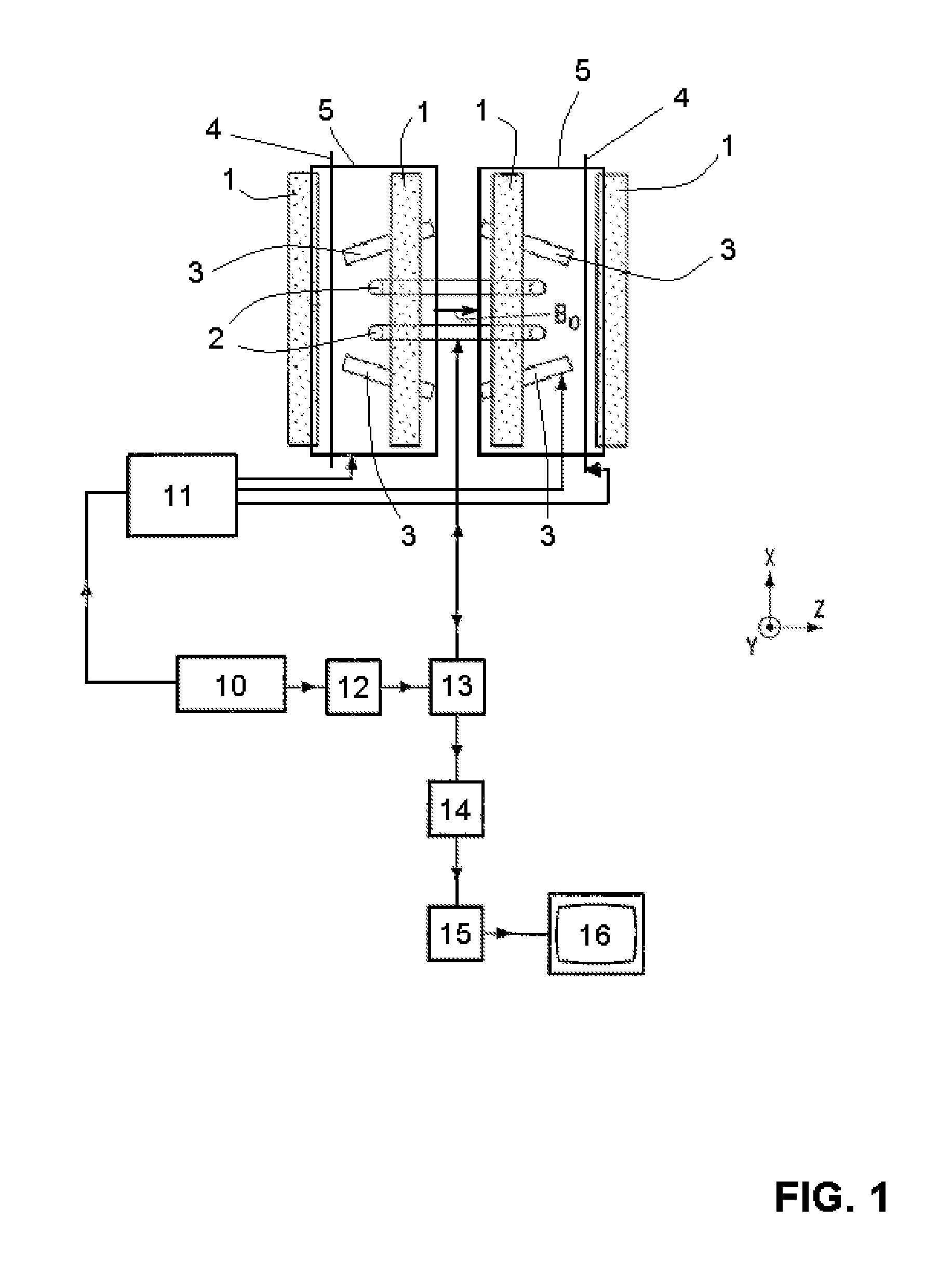
[0028]FIG. 1 shows substantial components of a magnetic resonance imaging system or a magnetic resonance scanner including an examination volume in which an object to be imaged is placed. The system comprises a main magnet system 1 for generating an essentially uniform and steady main magnetic field B0 in the z-direction for aligning the nuclear spins in the object to be imaged. An RF / MR transmit / receive antenna arrangement 2 is provided for transmitting RF signals for generating an RF magnetic alternating field B1 for exciting nuclear magnetic resonances and for receiving subsequent MR relaxation signals from the related nuclei of the object to be imaged. For the spatial selection and spatial encoding of the received MR relaxation signals emanating from the excited nuclei, the system also comprises a gradient magnet system with a plurality of gradient magnetic field coils 3, 4, 5 by which gradient magnetic fields in the orthogonal x-, y- and z-directions, respectively, are generate...


PUM


Abstract

The invention relates to a state space feedback controller operating in the digital domain for the regulation of the current supply to MRI gradient coils from a multiple-bridge PWM power amplifier. The Pl-controller comprises an integration part (for the integration of the difference between the demand current and the measured gradient coil current) and a subsequent P-controlled system which in turn comprises a delay compensator / stabilizer and a plant. The delay compensator / stabilizer comprises a multi-path feedback loop by means of which its digital output signal is fed back through delay blocks, on the one hand, and through filter units, on the other hand, whereby the filter units model the transfer functions of a gradient coil output filter for the gradient coil voltage and the output current of the amplifier inverter units, respectively. In the plant, a filter unit, which models the gradient coil transfer function, is connected in series to a delay chain for the delay of the measurement value of the gradient coil current.

Description

FIELD OF THE INVENTION[0001]The invention relates to a method and a digital amplifier system for operating an MRI (magnetic resonance imaging) gradient magnet system for generating gradient magnetic fields especially for spatially encoding MR (magnetic resonance) relaxation signals.BACKGROUND OF THE INVENTION[0002]In an MRI system or MR scanner, an examination object, usually a patient, is exposed to a uniform main magnetic field (B0 field) so that the magnetic moments of the nuclei within the examination object tend to rotate around the axis of the applied B0 field (Larmor precession) with a certain net magnetization of all nuclei parallel to the B0 field. The rate of precession is called Larmor frequency which is dependent on the specific physical characteristics of the involved nuclei, namely their gyromagnetic ratio, and the strength of the applied B0 field. The gyromagnetic ratio is the ratio between the magnetic moment and the spin of a nucleus.[0003]By transmitting an RF exci...

Claims


Application Information

Patent Timeline
IPC IPC(8): G01R33/385
CPCG01R33/3852
Inventor SCHEEL, THOMASHATTRUP, CHRISTIAN
Owner KONINKLIJKE PHILIPS ELECTRONICS NV
Why Eureka
Try Eureka