
Dose rate measuring apparatus

a technology of dose rate and measuring apparatus, which is applied in the direction of optical radiation measurement, instruments, x/gamma/cosmic radiation measurement, etc., can solve the problems of inability to respond to lack of information in an abrupt development of an event, and indirect transmission. , to achieve the effect of low energy consumption and high accuracy without deteriorating resolution

Inactive Publication Date: 2013-10-31
MITSUBISHI ELECTRIC CORP
View PDF3 Cites 8 Cited by
  • Summary
  • Abstract
  • Description
  • Claims
  • Application Information

AI Technical Summary

Benefits of technology

The invention is for a device that measures the amount of radiation in a sample. It can detect changes in the radiation caused by a reactor or by natural factors like rain or snow. The device uses a detector to capture the radiation, and a special analysis function to measure the peak wave height and the energy of the radiation. This analysis is done by a computer that calculates the dose rate and mean energy from the measured data. The device can also measure the accumulation of radiation over time, which allows for accurate measurements even at low energy levels. This invention is useful for monitoring radiation levels in various settings and can provide quick and accurate information to help determine the source of the radiation.

Problems solved by technology

However, there is a problem that a transmittance is indirect and difficult to understand in comparison with mean energy.
Also, the G(E) function method and the DBM method in the related art have a problem in responsivity to an abrupt development of an event.
Hence, a lack of information in an abrupt development of an event becomes a problem.
This poses a problem that resolution of a dose rate becomes rough or a count loss occurs when low-energy radiation comes in a burst.

Method used


Image

  • Dose rate measuring apparatus
  • Dose rate measuring apparatus
  • Dose rate measuring apparatus

Examples


first embodiment

[0022]Hereinafter, a dose rate measuring apparatus according to a first embodiment of the invention will be described. The apparatus shown in FIG. 1 is used, for example, to measure environmental γ (or X) rays and formed of a radiation detector 1, a pulse amplifier 2, a signal processing portion 3, and a memory and display device 4. The radiation detector 1 absorbs incident radiation and outputs an analog pulse having a wave height corresponding to energy thereof. The analog pulse is first amplified and wave-shaped in the pulse amplifier 2 to be readily processed in the latter stage and then inputted into the signal processing portion 3. The signal processing portion 3 performs computation processing by converting the analog pulse inputted therein to a digital signal. The computation result is saved in a recording medium of the memory and display device 4 and displayed thereon.

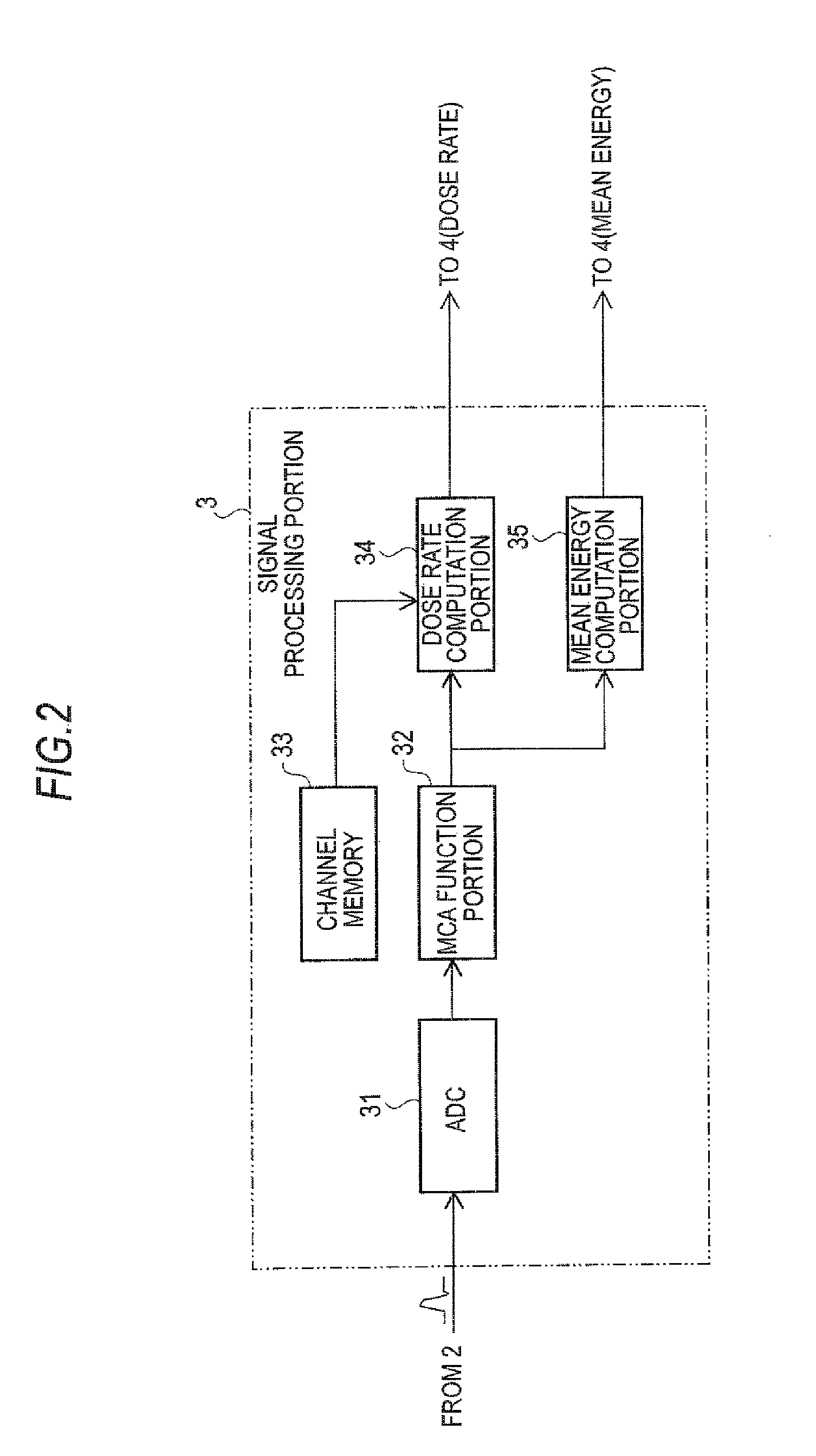
[0023]FIG. 2 shows the signal processing portion 3 in detail. An analog signal inputted into the signal pro...

second embodiment

[0028]A second embodiment of the invention will now be described. A dose rate measuring apparatus of the second embodiment is of the same configuration as the one shown in FIG. 1. The signal processing portion 3 in FIG. 1 described in the first embodiment above outputs the dose rate r1, the mean energy e1, and the count rate n1. However, another computation method is added in the second embodiment.

[0029]A signal processing portion 3 shown in FIG. 3 will now be described. A signal outputted from the pulse amplifier 2 is converted to a digital signal in an ADC 31 and then accumulated in an MCA function portion 32 as spectral information. From the spectral information, a dose rate, mean energy, and a count rate are calculated using a first dose rate computation portion 341 and a first mean energy computation portion 351 by the same methods used in the dose rate computation portion 34 and the mean energy computation portion 35 in the first embodiment above.

[0030]The spectral information...

third embodiment

[0033]A third embodiment will now be described. A dose rate measuring apparatus of the third embodiment is of the same configuration as the one shown in FIG. 1. FIG. 4 shows a signal processing portion 3 of the third embodiment. The signal processing portion 3 shown in FIG. 4 converts an output of the pulse amplifier 2 to a digital form in an ADC 31. The converted signal is subjected to radiation energy spectral analysis in an MCA function portion 32 by allocating a channel corresponding to a wave height value and counting the wave height value channel by channel. On the basis of spectral information thus obtained and numerical values of the G(E) functions corresponding to the respective channels of the MCA function portion 32 and stored in a channel memory 33, a dose rate and mean energy are measured in a dose rate computation portion 34 and a mean energy computation portion 35, respectively, by the same methods as those used in the first embodiment above.

[0034]In the third embodim...


PUM


Abstract

A radiation detector outputs an analog pulse for incident radiation, and a signal processing portion is furnished with a wave height measuring function of converting the analog pulse inputted therein to a digital form and then measuring a peak wave height of the analog pulse and a wave height spectrum measuring function of measuring a wave height spectrum on the basis of measured wave height data, computes a dose rate and mean energy on the basis of measured wave height spectral data, and outputs computation results. The signal processing portion computes the dose rate and the mean energy on the basis of the wave height spectral data in a same wave height range on a same time axis. It thus becomes possible to provide accurate information based on which to determine whether a rise in dose rate is contributed by natural radon and thoron or contributed by a reactor facility.

Description

BACKGROUND OF THE INVENTION[0001]1. Field of the Invention[0002]The present invention relates to a dose rate measuring apparatus introduced to an environmental radiation monitoring post or a portable monitoring post set up within a nuclear-related facility and in a surrounding area to measure a dose rate that is an amount of radiation per unit time.[0003]2. Background Art[0004]For a dose rate measuring apparatus in the related art, there are a G(E) function method and a DBM (Discrimination Biased Modulation) method as means for finding a dose rate or the like on the basis of a wave height of a detection pulse. According to the G(E) function method, an energy spectrum of radiation is obtained by an MCA (Multi-Channel Analyzer) and a dose rate is obtained by multiplying energy conversion factors (hereinafter, referred to as the G(E) functions) that are energy conversion factors corresponding to energy of respective channels of the obtained spectrum by the numbers of counts of the resp...

Claims


Application Information

Patent Timeline
Patent Type & Authority Applications(United States)
IPC IPC(8): G01T1/02
CPCG01T1/17G01T1/178G01T3/085
Inventor AIBA, TOSHIHIDEMOTEKI, KENICHI
Owner MITSUBISHI ELECTRIC CORP
Learn More