
Universal construction bracket method and apparatus

a technology of universal brackets and brackets, applied in the direction of rod connections, fastening means, constructions, etc., can solve the problems of frequent time-consuming, costly and labor-intensive use of such conventional connectors, and achieve the effects of easy manufacturing and use, corrosion resistance, and easy scaling

Inactive Publication Date: 2013-10-03
CAMPBELL JOHN HOLLAND
View PDF14 Cites 9 Cited by
  • Summary
  • Abstract
  • Description
  • Claims
  • Application Information

AI Technical Summary

Benefits of technology

The present invention is a universal bracket system for constructing buildings, dwellings, structures, and other objects. It is designed to interlock with other brackets to join or connect structural members. The system allows for sturdy and strong connections that can withstand lateral loads (wind and seismic) and resist corrosion. It also provides required bearing area for beams and uplift resistance. The bracket system is easy to use, affordable, and can be customized for different projects. It reduces material waste, minimizes post cuts and drill hole, and is suitable for repairs and remodeling. Overall, the universal bracket system of the present invention meets applicable code requirements and provides efficient and precision construction.

Problems solved by technology

Unfortunately, such existing connectors have different configurations for different uses.
Use of such conventional connectors is frequently time consuming, costly and labor intensive.

Method used


Image

  • Universal construction bracket method and apparatus
  • Universal construction bracket method and apparatus
  • Universal construction bracket method and apparatus

Examples


Embodiment Construction

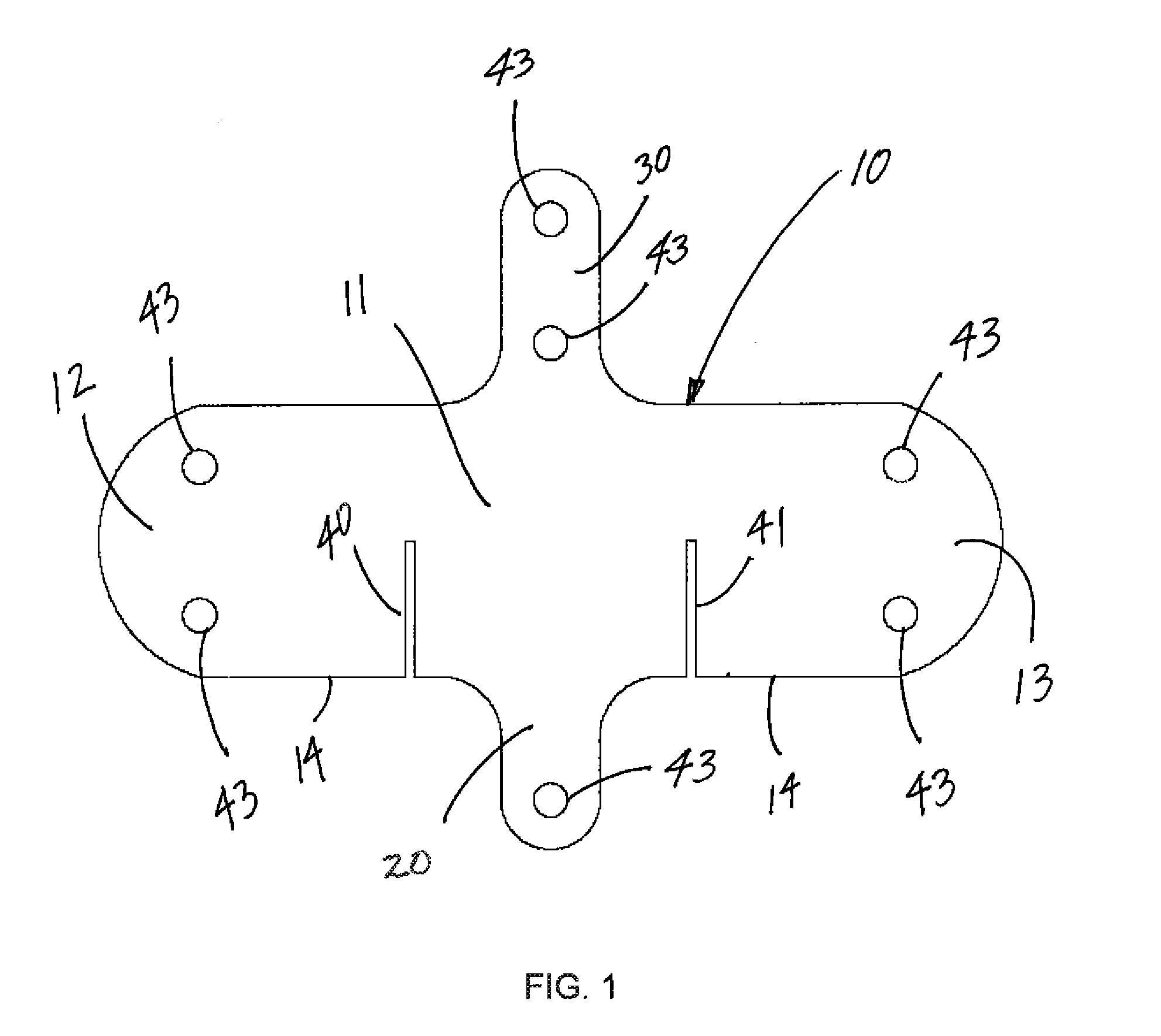
[0036]FIG. 1 depicts a side view of a primary bracket plate member 10 of the present invention. Said primary bracket plate member 10 is substantially planar and constructed of steel or other rigid material having desired strength and appearance characteristics. The thickness of said primary bracket plate member 10 can be beneficially adjusted to provide desired strength characteristics, as well as appearance for applications in which such primary bracket plate member 10 will be visible.

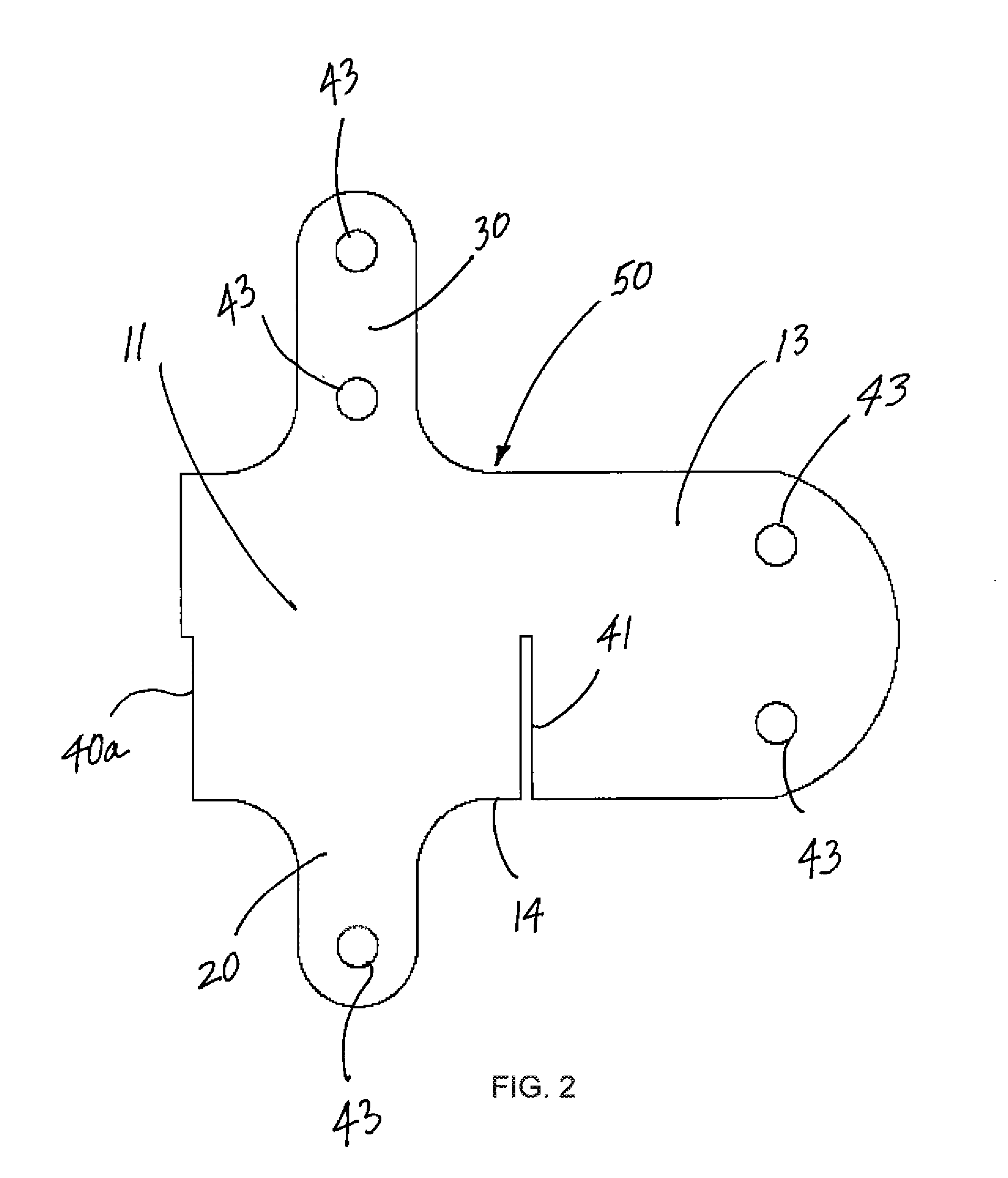
[0037]Said primary bracket plate member comprises a central body section 11 having a first lateral flange member 12 and a second lateral flange member 13. Said lateral flange members 12 and 13 can include holes or apertures 43 extending through said flange members. In the preferred embodiment, said holes 43 disposed through said lateral flange members 12 and 13 are oriented in vertically-aligned pairs, with one pair of vertically aligned holes 43 extending through each lateral flange member. Said hole...


PUM


Abstract

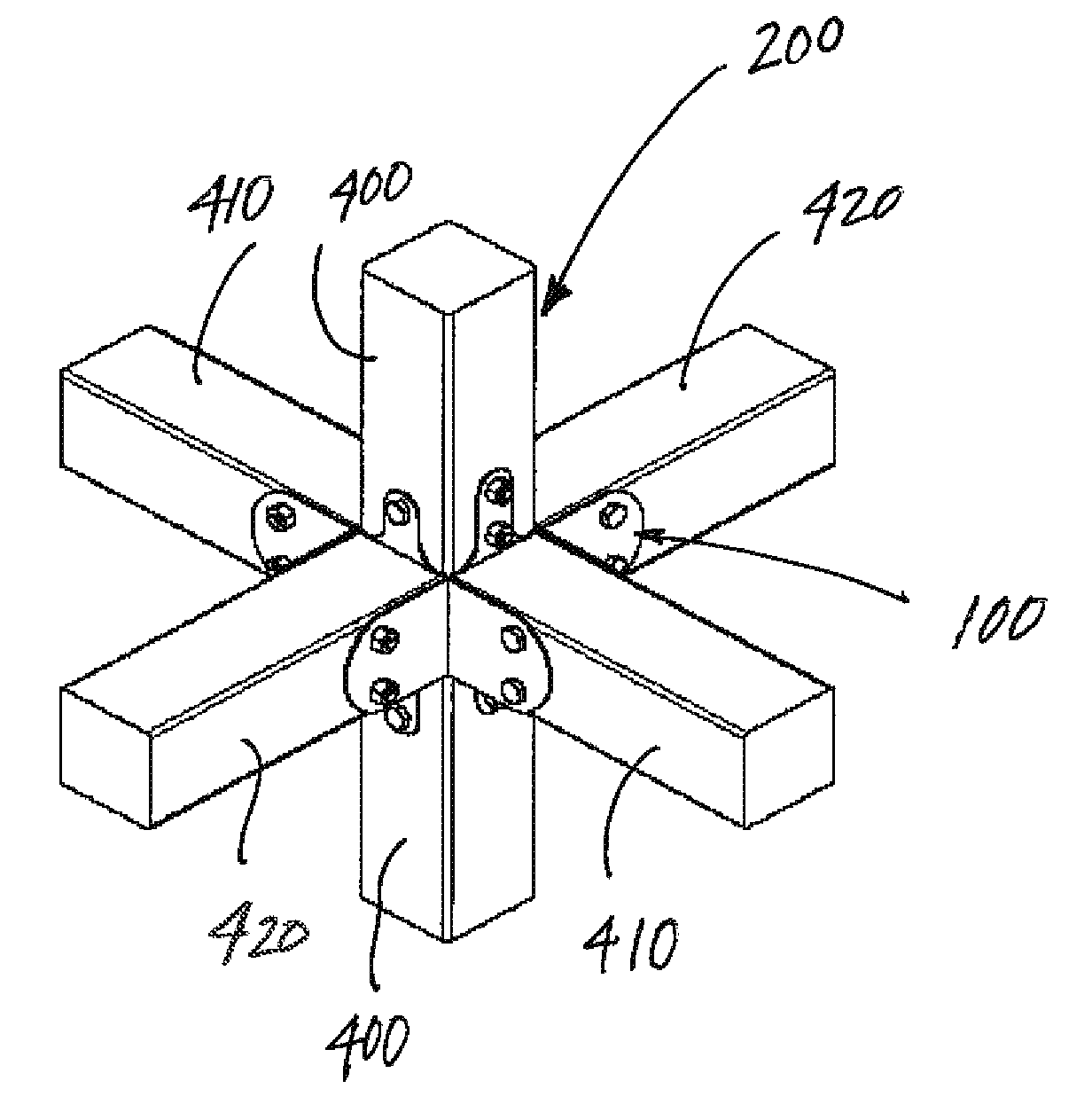
A universal bracket system can be used to create multiple interlocking bracket assemblies for construction of buildings, dwellings, structures and other objects. A primary planar bracket plate member has flange extensions and holes for bolts or other fasteners. Multiple supplementary bracket plate members are variations of the primary bracket plate member. A ridge bracket plate member is provided. Primary and supplementary plate members, as well as the ridge bracket plate member, can be combined in multiple interlocking configurations to create brackets for connecting structural members into many different connection joints.

Description

CROSS REFERENCES TO RELATED APPLICATION[0001]Priority of U.S. Provisional Patent Application Ser. No. 61 / 613,553, filed Mar. 21, 2012, incorporated herein by reference, is hereby claimed.STATEMENTS AS TO THE RIGHTS TO THE INVENTION MADE UNDER FEDERALLY SPONSORED RESEARCH AND DEVELOPMENT[0002]NONEBACKGROUND OF THE INVENTION[0003]1. Field of the Invention[0004]The present invention pertains to a universal bracket system. More particularly, the present invention pertains to a universal bracket system that can be used to join timbers or other structural members for the construction of buildings and / or other structures. More particularly still, the present invention pertains to a universal bracket system comprising bracket plates that can be optionally interlocked to form different brackets which, in turn, can be used to form multiple joint configurations or junction points for structural members.[0005]2. Brief Description of the Prior Art[0006]During the construction of buildings, dwell...

Claims


Application Information

Patent Timeline
Patent Type & Authority Applications(United States)
IPC IPC(8): F16B7/00
CPCF16B7/00E04B2001/2676Y10T403/3906F16B7/185E04B1/2604F16B7/048F16B9/058F16B9/052
Inventor CAMPBELL, JOHN HOLLAND
Owner CAMPBELL JOHN HOLLAND
Learn More