
Papermaking press felt and papermaking press apparatus

Inactive Publication Date: 2005-08-04
ICHIKAWA ELECTRIC CO LTD
View PDF3 Cites 11 Cited by
  • Summary
  • Abstract
  • Description
  • Claims
  • Application Information

AI Technical Summary

Benefits of technology

[0014] An environment where felt is used is becoming more and more harsh in recent years, because of an increase in operating speed of a papermaking machine associated with the progress in production efficiency of the paper and an increase in pressure in a press section. Accordingly, such an increase in the speed of a papermaking machine and in pressure of a roll or a shoe in a pressing section for improving productivity, which is the latest trend with respect to papermaking machines, has incurred a drawback that the papermaking press felt becomes flattened by the high pressure and thereby loses its water permeability and capability of recovery against compaction, thus significantly degrading its dewatering performance.

Problems solved by technology

An environment where felt is used is becoming more and more harsh in recent years, because of an increase in operating speed of a papermaking machine associated with the progress in production efficiency of the paper and an increase in pressure in a press section.
Accordingly, such an increase in the speed of a papermaking machine and in pressure of a roll or a shoe in a pressing section for improving productivity, which is the latest trend with respect to papermaking machines, has incurred a drawback that the papermaking press felt becomes flattened by the high pressure and thereby loses its water permeability and capability of recovery against compaction, thus significantly degrading its dewatering performance.
Accordingly, it is well known that the staple fiber of the felt structure is susceptible to flattening.

Method used


Image

  • Papermaking press felt and papermaking press apparatus
  • Papermaking press felt and papermaking press apparatus
  • Papermaking press felt and papermaking press apparatus

Examples


example 1

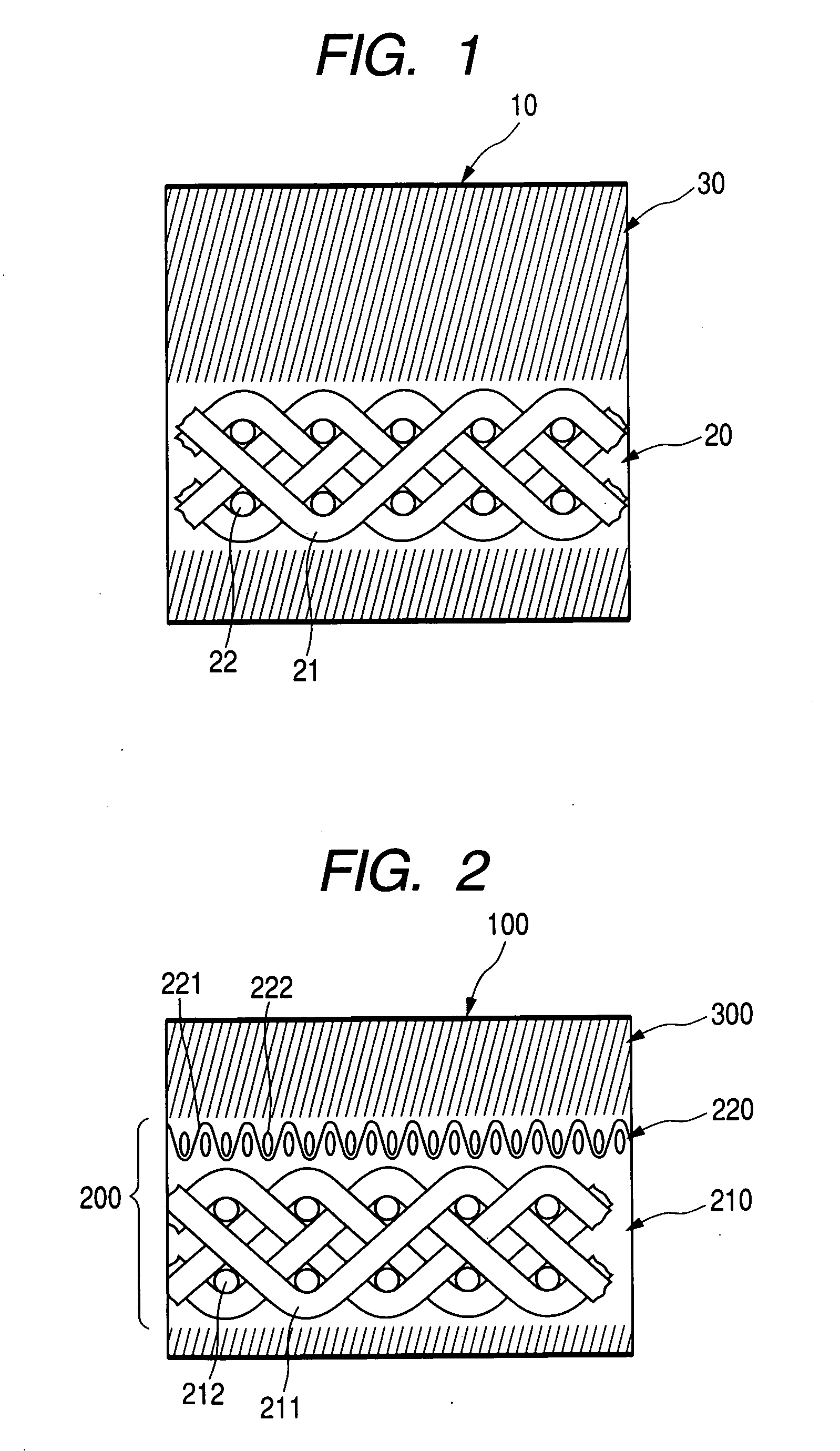
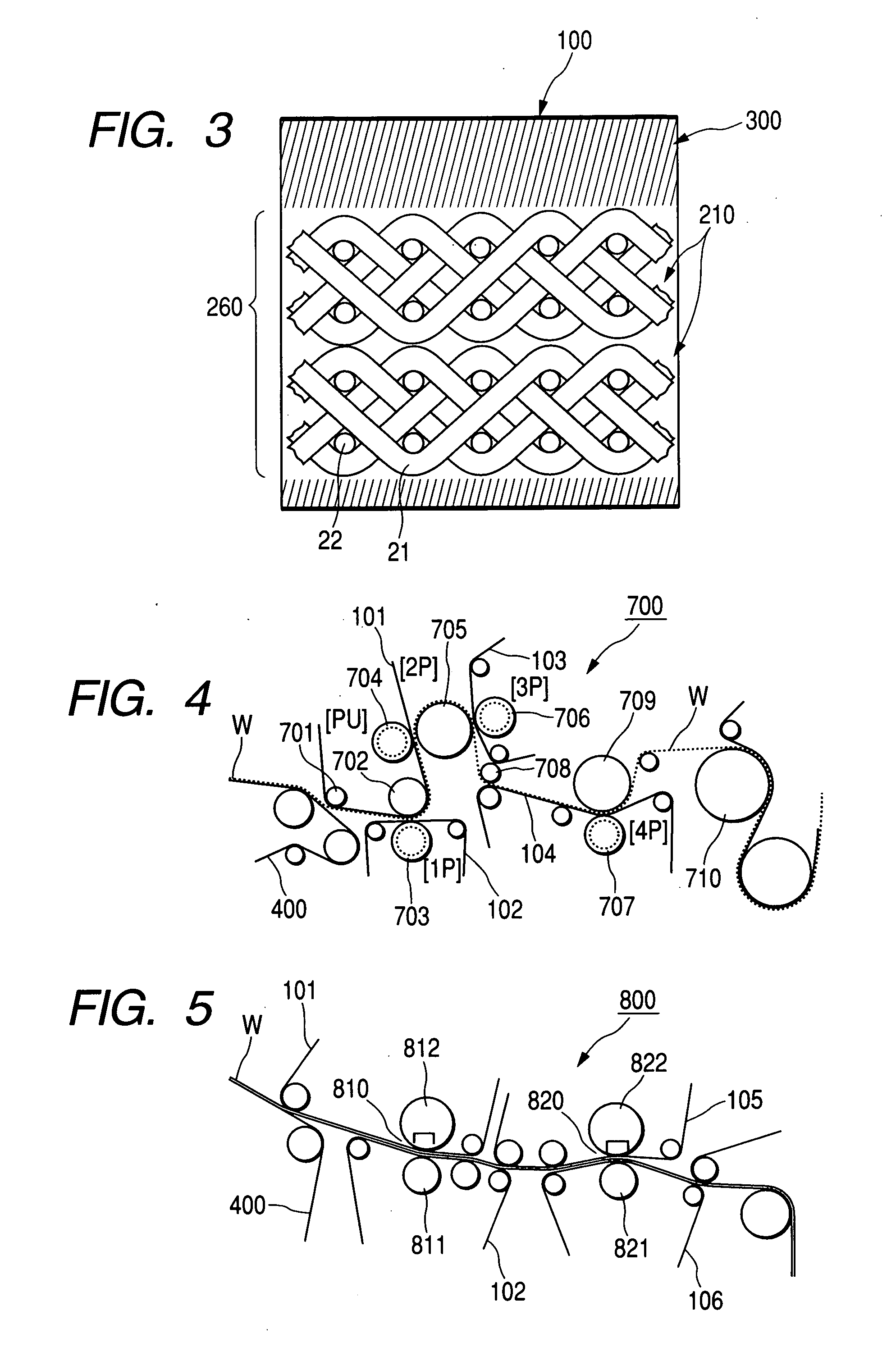
[0070] As shown in FIG. 2, a felt has been fabricated by layering the following woven fabric 220 as the base material B on the base material A (210) to constitute the base material 200, and further forming the staple fiber layer 300 (11 dtex, 600 g / m2)

Structure of the Woven Fabric 220:

[0071] (1) MD yarn: The twine specified below has been employed. [0072] (a) Twisting condition: “2 / 2 / 220”[0073] (b) Preliminary twisting: S-twist, 42 times per meter [0074] (c) Final twisting: Z-twist, 30 times per meter [0075] (d) Twisting ratio (preliminary / final): 1.40 [0076] (2) CD yarn: single yarn (fineness 330 dtex) [0077] (3) Weaving: [0078] MD yarn: 40 rows / 5 cm, CD yarn: 34 rows / 5 cm 3 / 1 plain endless single woven

example 2

[0079] A felt of a similar structure to that of the example 1 has been fabricated, except that the following woven fabric 230 has been employed as the base material B instead of the woven fabric 220. In other words, 230 is layered instead of 220 in FIG. 2.

Structure of the Woven Fabric 230:

[0080] (1) MD yarn, CD yarn: The same as those of example 1. [0081] (2) Weaving: [0082] MD yarn: 40 rows / 5 cm, CD yarn: 34 rows / 5 cm [0083] 3 / 1 plain single woven with an end closed, wound twice to constitute the layered woven fabric 230.

example 3

[0084] A felt of a similar structure to that of the example 2 has been fabricated, except that the woven fabric 240 in which the MD yarn and the CD yarn are replaced with each other has been employed as the base material B, instead of the woven fabric 230. In other words, 240 is layered instead of 220 in FIG. 2.


PUM


Abstract

A papermaking press felt includes a plurality of base materials of an identical or a different type; and a fiber web layered on one or both faces of at least one of the base materials and integrally entwined therewith by needling. At least one of the base materials is a woven fabric including a machine direction (MD) yarn and a cross-machine direction (CD) yarn, such that one thereof is a twine made from a filament having a fineness of 50 to 250 dtex, and the other thereof is a single yarn having a fineness of 50 to 600 dtex.

Description

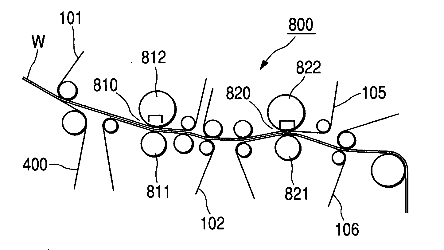
BACKGROUND OF THE INVENTION [0001] 1. Field of the Invention [0002] The present invention relates to a papermaking press felt (hereinafter simply referred to as “felt” as the case may be) and a papermaking press apparatus to be used in a papermaking machine. More particularly, the present invention relates to a papermaking press felt to be pressed in a pressing section of the papermaking machine so as to squeeze water out of a wet paper web, and to a papermaking press apparatus. [0003] 2. Background Art [0004] A papermaking machine is provided with a papermaking press apparatus (hereinafter simply referred to as “press apparatus” as the case may be), which dewaters a wet pulp (wet paper web) while it presses in its pressing section formed in a paper layer forming apparatus. Moisture in the wet paper web is squeezed out by applying a pressure thereto with the press apparatus. [0005] For example, FIG. 4 schematically shows a configuration of a pressing section 700 of a conventional pa...

Claims


Application Information

Patent Timeline
IPC IPC(8): D21F3/04D21F7/08
CPCD21F7/083D21F3/045D21F7/08
Inventor KOBAYASHI, YASUHIKOODA, HIROYUKIONIKUBO, AKIRA
Owner ICHIKAWA ELECTRIC CO LTD
Learn More