Electric connector
a technology of electrical connectors and connector terminals, applied in the direction of coupling devices, coupling devices, coupling devices, etc., can solve the problems of circuit board p deformation, defective electrical contact between circuit board p and the connector terminal, and ensure the contact stability. , the effect of preventing the reduction of the contact load
- Summary
- Abstract
- Description
- Claims
- Application Information
AI Technical Summary
Benefits of technology
Problems solved by technology
Method used
Image
Examples
first embodiment
[0044]An electrical connector (hereinafter, called “a card edge connector”) in accordance with the first embodiment of the present invention is described hereinbelow with reference to the drawings.
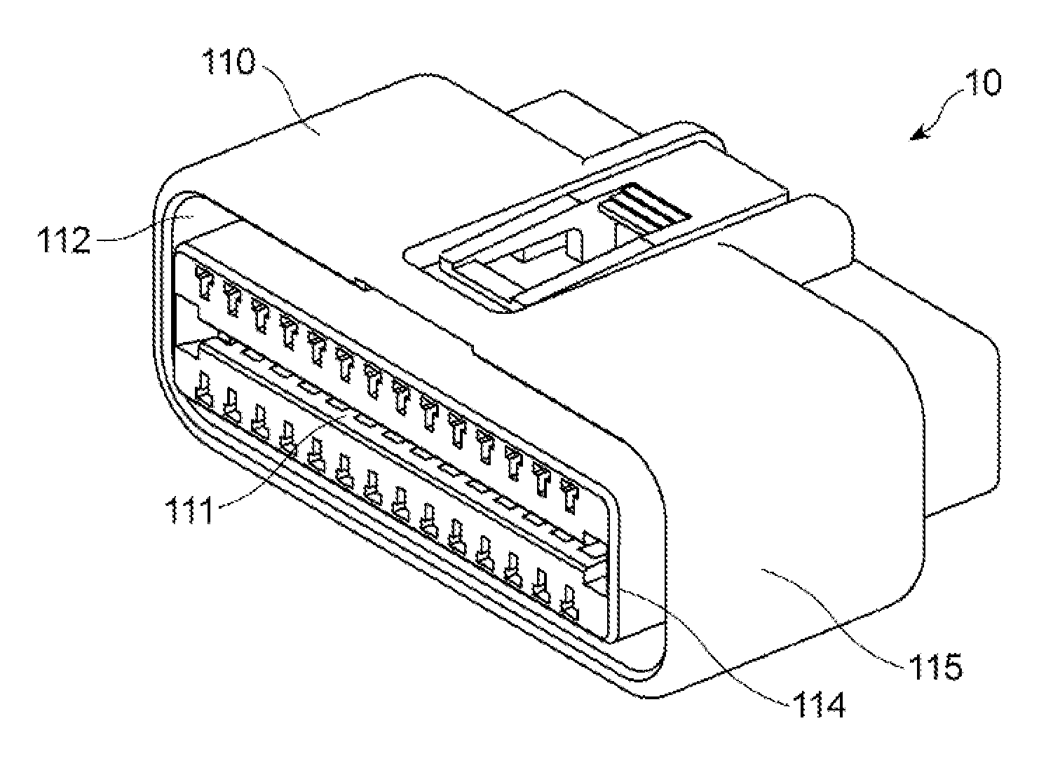
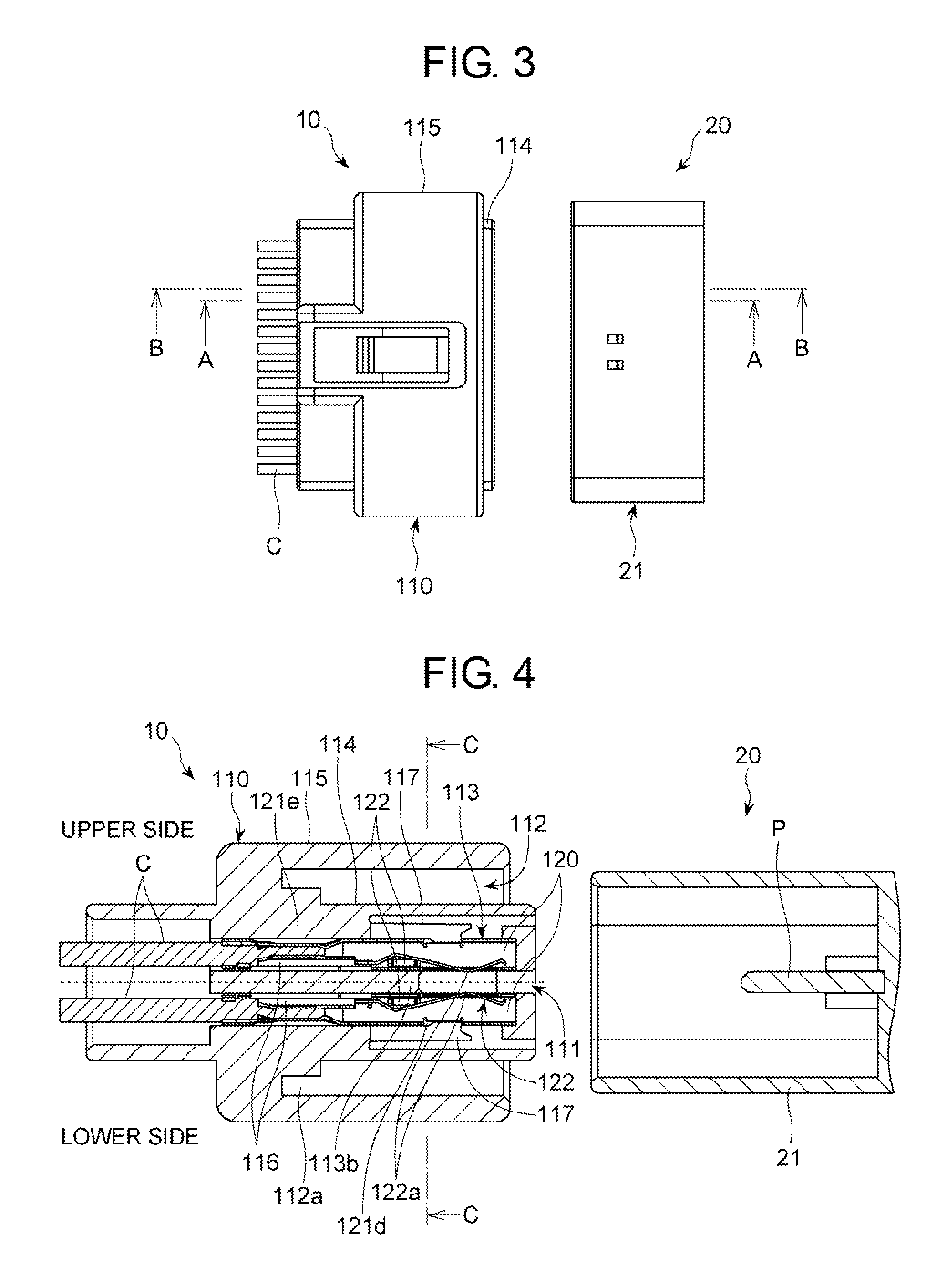
[0045]As illustrated in FIGS. 1 to 3, when a connector 20 equipped in a metal case including therein electronic devices used for an automobile is inserted into a card edge connector 10 in accordance with the first embodiment of the present invention, the card edge connector 10 electrically connects the electronic devices to cables C electrically connected to the card edge connector 10.
[0046]As illustrated in FIGS. 4 to 7, the card edge connector 10 includes a connector housing 110 and a plurality of connector terminals 120.
[0047]The connector housing 110 is a resin-molded product. The connector housing 110 is designed to include a slot 111 into which a circuit board P of the connector 20 is to be inserted, a circular slot 112 into which a connector housing 21 of the connector 20 is to be i...
second embodiment
[0075]FIG. 10 is a cross-sectional view of a card edge connector in accordance with the second embodiment of the present invention.
[0076]Parts or elements that correspond to those of the card edge connector in accordance with the first embodiment have been provided with the same reference numerals, operate in the same manner as corresponding parts or elements in the first embodiment, unless explicitly explained hereinbelow, and are not explained in detail.
[0077]In the card edge connector in accordance with the second embodiment, the linear grooves 116 are formed at opposite sidewalls of the partition wall 113a at a different height from each other, as illustrated in FIG. 10. Specifically, the linear groove 116 formed at a left sidewall of a certain partition wall 113a is situated lower than the linear groove 116 formed at a right sidewall of the partition wall 113a, for instance. In other words, the linear groove 116 formed at a left sidewall of a certain partition wall 113a is situ...
third embodiment
[0080]FIG. 11 is a cross-sectional view of a card edge connector in accordance with the third embodiment of the present invention.
[0081]Parts or elements that correspond to those of the card edge connector in accordance with the first embodiment have been provided with the same reference numerals, operate in the same manner as corresponding parts or elements in the first embodiment, unless explicitly explained hereinbelow, and are not explained in detail.
[0082]In the card edge connector in accordance with the third embodiment, a combination of the linear grooves 116 and the projections 121c in a first terminal space 113 is located at a different height from a height of a combination of the linear grooves 116 and the projections 121c in a second terminal space 113 located adjacent to the first terminal space 113.
[0083]The projections 121c of the sheath 120 are formed in accordance with the linear grooves 116. Accordingly, the sheath 120 corresponding to the first terminal space 113 i...
PUM
 Abstract
Description
Claims
Application Information
 - R&D
- Intellectual Property
- Life Sciences
- Materials
- Tech Scout
- Unparalleled Data Quality
- Higher Quality Content
- 60% Fewer Hallucinations
Browse by: Latest US Patents, China's latest patents, Technical Efficacy Thesaurus, Application Domain, Technology Topic, Popular Technical Reports.
© 2025 PatSnap. All rights reserved.Legal|Privacy policy|Modern Slavery Act Transparency Statement|Sitemap|About US| Contact US: help@patsnap.com


