
System and method for identification of pipe defects that leak

a technology of leakage detection and system, applied in the direction of structural/machine measurement, using reradiation, instruments, etc., can solve the problems of increasing the cost of operating the pipe, creating hazards, and affecting the inspection of sewer systems and other underground pipes, so as to reduce the leakage of fluids, facilitate and facilitate operation, the effect of high data accuracy

Active Publication Date: 2013-08-22
ELECTRO SCAN
View PDF1 Cites 10 Cited by
  • Summary
  • Abstract
  • Description
  • Claims
  • Application Information

AI Technical Summary

Benefits of technology

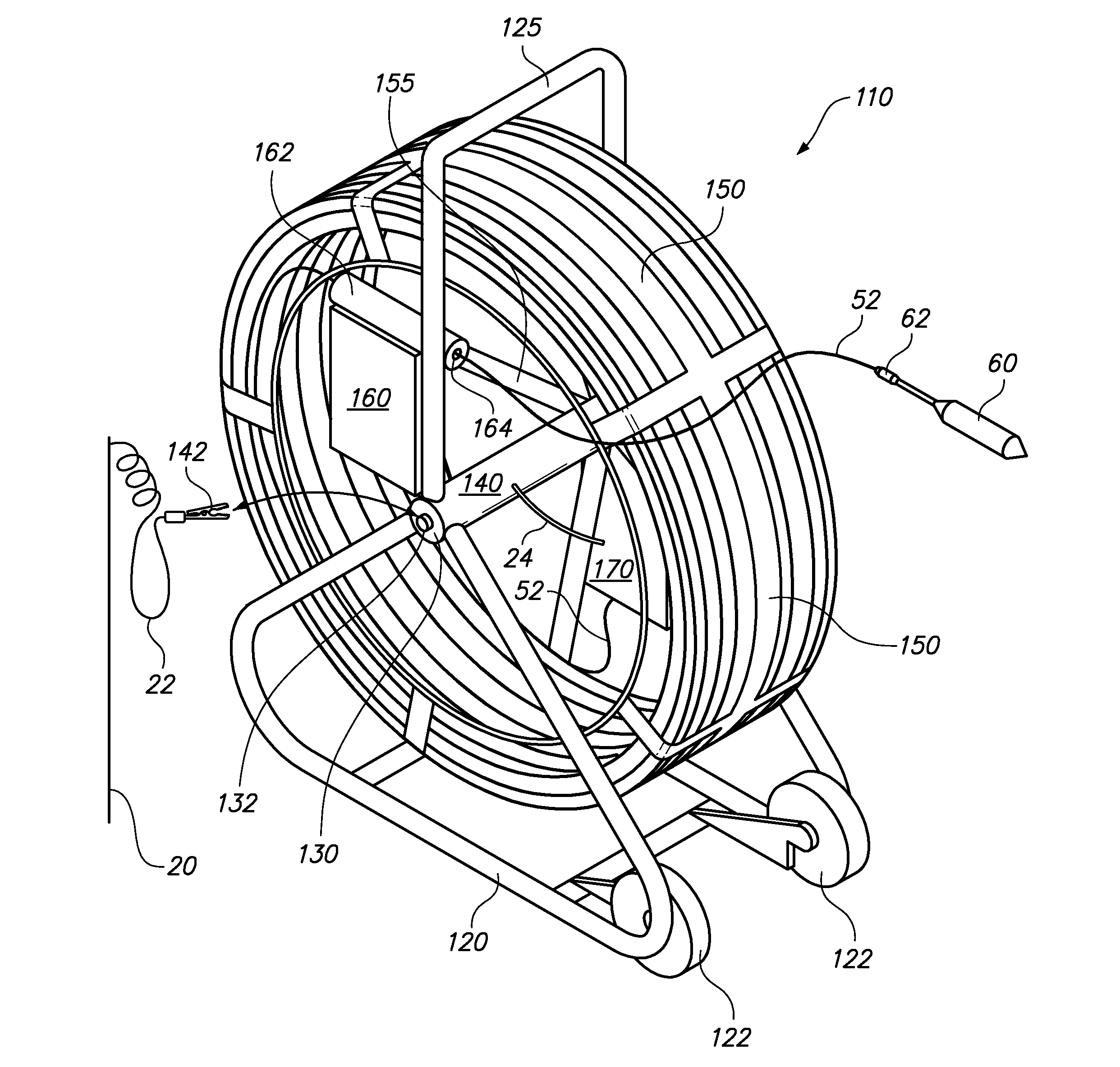
The present invention relates to a system and apparatus for efficiently and accurately gathering data associated with underground pipe conditions using the electroscan method. The system includes a reel with a grounded cable and a hub for rotating and maintaining a grounded electric connection. The system can support the cable as it is deployed and the probe is drawn through a pipe being evaluated. The invention aims to minimize leakage of fluids into or out of pipelines by providing an effective method and apparatus for evaluating underground pipe condition and managing cable associated with an electroscan underground pipe evaluation system for convenient and easy operation and to acquire highly precise data.

Problems solved by technology

Sewer systems and other underground pipes can be difficult to inspect due to their hidden location.
Leaks in such pipes can increase costs associated with operating the pipe, and potentially create hazards.
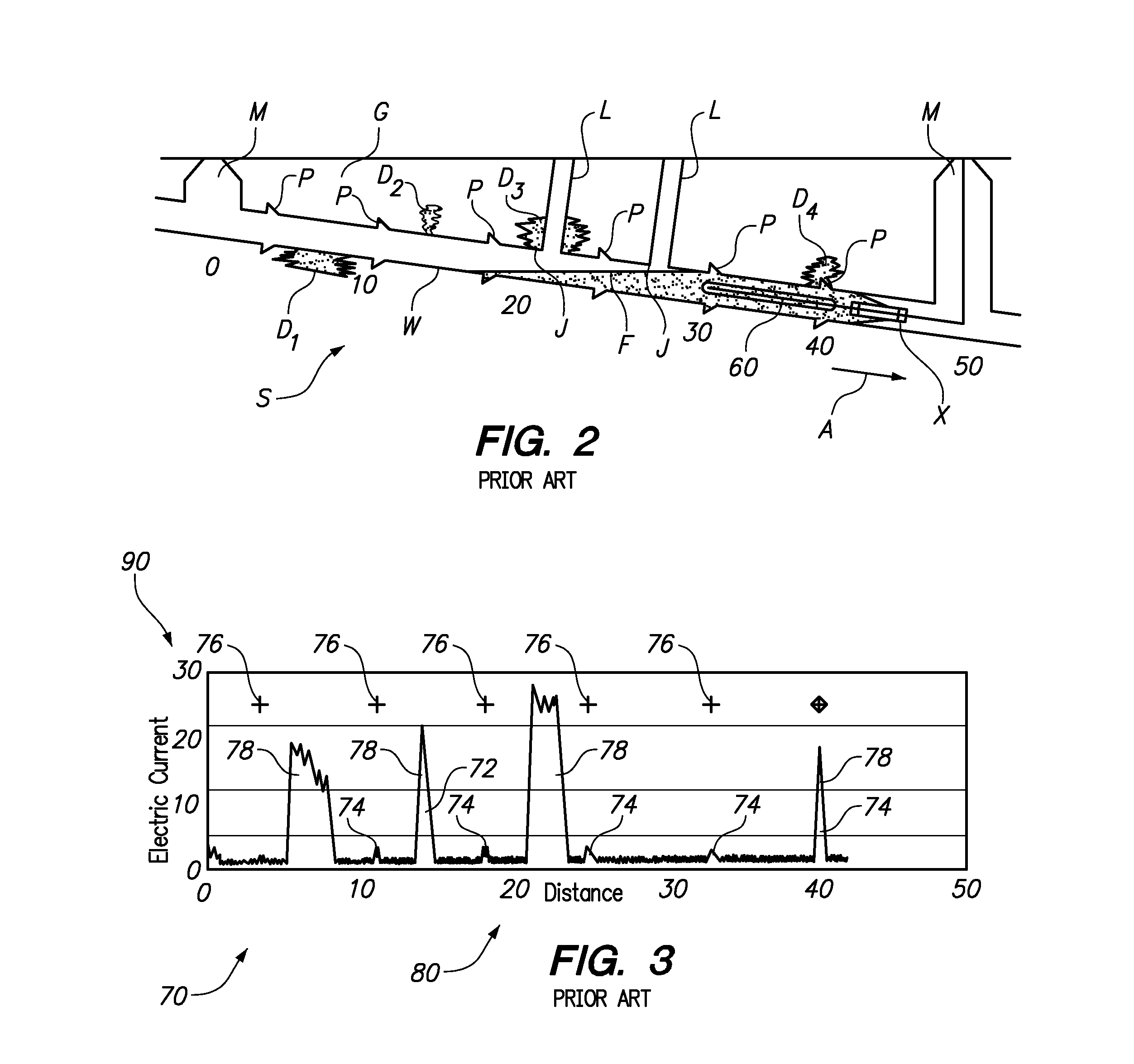
Operation of the electro scan method can be difficult in that there is a challenge associated with accurately correlating the current amplitude data with the probe position.
Repairs might then be done in the wrong location or further analysis conducted in the wrong location, wasting time, resources and increasing the cost of further analysis and repairs.
To precisely correlate probe position with current amplitude data can be a time intensive and laborious process, thus magnifying the resources required to analyze a section of pipe.
Furthermore, raw data gathered from the current meter and probe position often need significant conditioning before it can be most meaningfully evaluated by personnel.

Method used


Image

  • System and method for identification of pipe defects that leak
  • System and method for identification of pipe defects that leak
  • System and method for identification of pipe defects that leak

Examples


Embodiment Construction

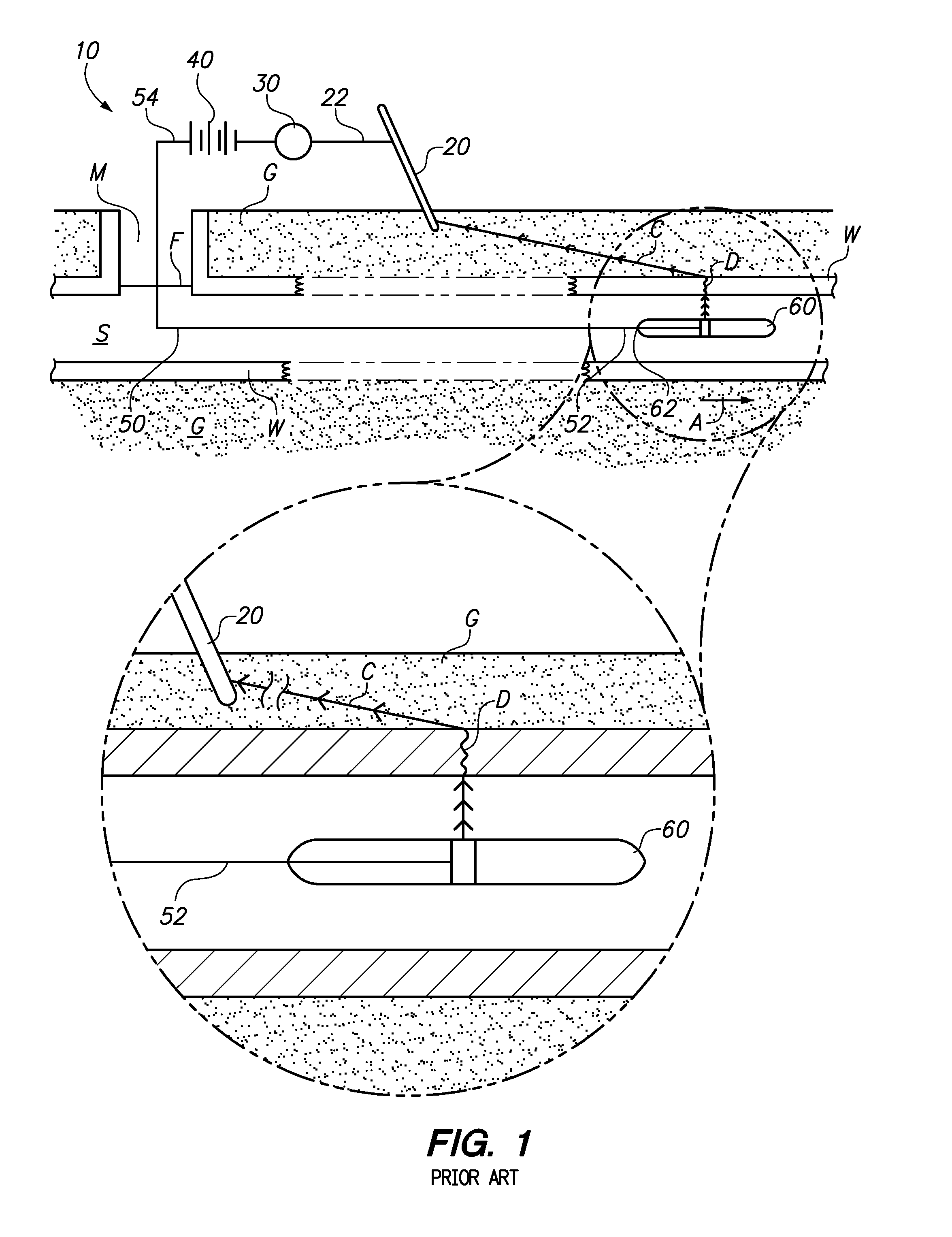
[0029]Referring to the drawings, wherein like reference numerals represent like parts throughout the various drawing figures, reference numeral 10 is directed to a system for identification of pipe defects. The system 10 (FIG. 1) is consistent with a prior art system described in ASTM (ASTM International, formerly known as “American Society for Testing and Materials”) Standard F2550-06 described as “Standard Practice for Locating Leaks in Sewer Pipes Using Electroscan—the Variation of Electric Current Flow Through the Pipe Wall.” This system 10 can be utilized in underground pipes such as a sewer S (FIG. 2) by passing a probe 60 through the sewer S pipe, such as between adjacent manholes M to detect defects D in the pipe wall W. The system incorporates a reel assembly 110 (FIGS. 4 and 5) and data handling and processing (FIG. 6) with a smartphone 190 or other on-site processor, as well as a remote processing location 200, for efficient and accurate data handling and overall database...


PUM


Abstract

The system utilizes electroscan equipment including a voltage source and current meter with a cable having one end grounded and one end having an electric probe thereon sized to fit within an underground pipe. The probe is able to complete an electric circuit back to ground when the probe is adjacent a defect through which electric currents can pass, thus producing varying electric current. A cable reel is provided with portions of the cable supported thereon and with a cable distance sensor coupled to the reel along with the current meter and voltage source in the form of a battery. The current meter and distance sensor transmit wireless signals to an on-site processor, such as a smartphone, for on-site data evaluation. Such unconditioned data is also transmitted to a remote location for conditioning of the data and retransmission of the conditioned data back to the on-site processor.

Description

CROSS-REFERENCE TO RELATED APPLICATIONS[0001]This application claims benefit under Title 35, United States Code §119(e) of U.S. Provisional Application No. 61 / 633,810 filed on Feb. 16, 2012, U.S. Provisional Application No. 61 / 633,811 filed on Feb. 16, 2012 and U.S. Provisional Application No. 61 / 689,248 filed on Jun. 1, 2012.FIELD OF THE INVENTION[0002]The following invention relates to systems and methods for detecting defects in underground pipes, such as sewer pipes or water pipes which have a potential to leak. More particularly, this invention relates to systems and methods which involve establishing if electric current flows between ground adjacent the pipe and an interior of the pipe, which circuit increases in current amplitude when an electric probe passing through a pipe filled with electrically conductive fluid approaches defects in the pipe.BACKGROUND OF THE INVENTION[0003]Sewer systems and other underground pipes can be difficult to inspect due to their hidden location...

Claims


Application Information

Patent Timeline
IPC IPC(8): G01M3/40
CPCG01M5/0025G01M5/0033G01M3/40G01N27/60G01M5/0083
Inventor HANSEN, CHARLESHARRIS, ROBERT JACKSON
Owner ELECTRO SCAN
Learn More