Radially notched piston rings

Active Publication Date: 2016-03-10
TOTAL SEAL
View PDF0 Cites 5 Cited by
  • Summary
  • Abstract
  • Description
  • Claims
  • Application Information

AI Technical Summary

Benefits of technology

The invention is a piston ring that is used to seal and minimize fluid leakage between two parts that move relative to each other. The piston ring is a tensionable annular member with inner and outer surfaces, a contact surface, an end gap, and a plurality of notches formed in its inner surface. The notches are spaced-apart along the length of the piston ring and are designed to inhibit crack propagation when the piston ring is tensioned. The spacing between each notch is the same, and each notch has a unique design that includes a notch width, a notch length, and a notch radius. The design of the notches allows for a constant or variable tension-relieving property of the piston ring. The technical effect of this invention is to provide a reliable and effective sealing solution for minimizing fluid leakage between two parts that move relative to each other.

Problems solved by technology

Frequently, substantial clearance is required.
Having an inherent tendency to expand, the ring maintains constant tension for attendant sealing against the sidewall of the cylinder as the bore increases in diameter as a result of wear.
In general, less than optimum output of the apparatus results from loss of pressure or compression of the fluid.
Other deleterious effects are unique to the particular apparatus.
In an internal combustion engine, for example, contaminating by-products of combustion suspended in the blow-by gases are carried into the lubricating system, which harms components throughout the engine and produces an attendant power loss.
In internal combustion engines, piston rings that fail to seal the pistons to the cylinders that result in the attendant blow-by can reduce the engine's power by up to forty percent depending on the engine's displacement, compression ratio and speed.
For various reasons, annular seals of the foregoing character are not entirely satisfactory.
For example, in an assembly wherein the rail resides within the seal member and exerts an expansive force, excessive friction is generated against the sidewall of the bore.
An angled rail is subject to vibration, commonly known as ring flutter, when used in connection with a rapidly reciprocating piston.
Seal assemblies of the foregoing type tend to be inherently heavy and highly tensioned so as to be prone to wear and prone to produce cylinder distortion.
The tension exerted against the sidewall of the bore is often unnecessarily high, which results in unwanted and premature wear than can compromise the seal leading to power loss and fuel inefficiency in internal combustion engines.
The tension exerted against the sidewall of the bore is also uneven, which leads to prolonged wear-in and seating.
Even after seating, the irregular tension exerted by the annular seal against the sidewall of the bore persists, which results in the irregular wear of the annular seal and the sidewall of the bore, which can produce power loss and poor fuel economy.
Low tension piston rings, being thinner than standard piston rings, unfortunately tend to become distorted when exposed to extreme engine heat, which can compromise the seal with the cylinder resulting in blow-by, loss of power, and poor fuel economy.

Method used


Image

  • Radially notched piston rings
  • Radially notched piston rings
  • Radially notched piston rings

Examples


Embodiment Construction

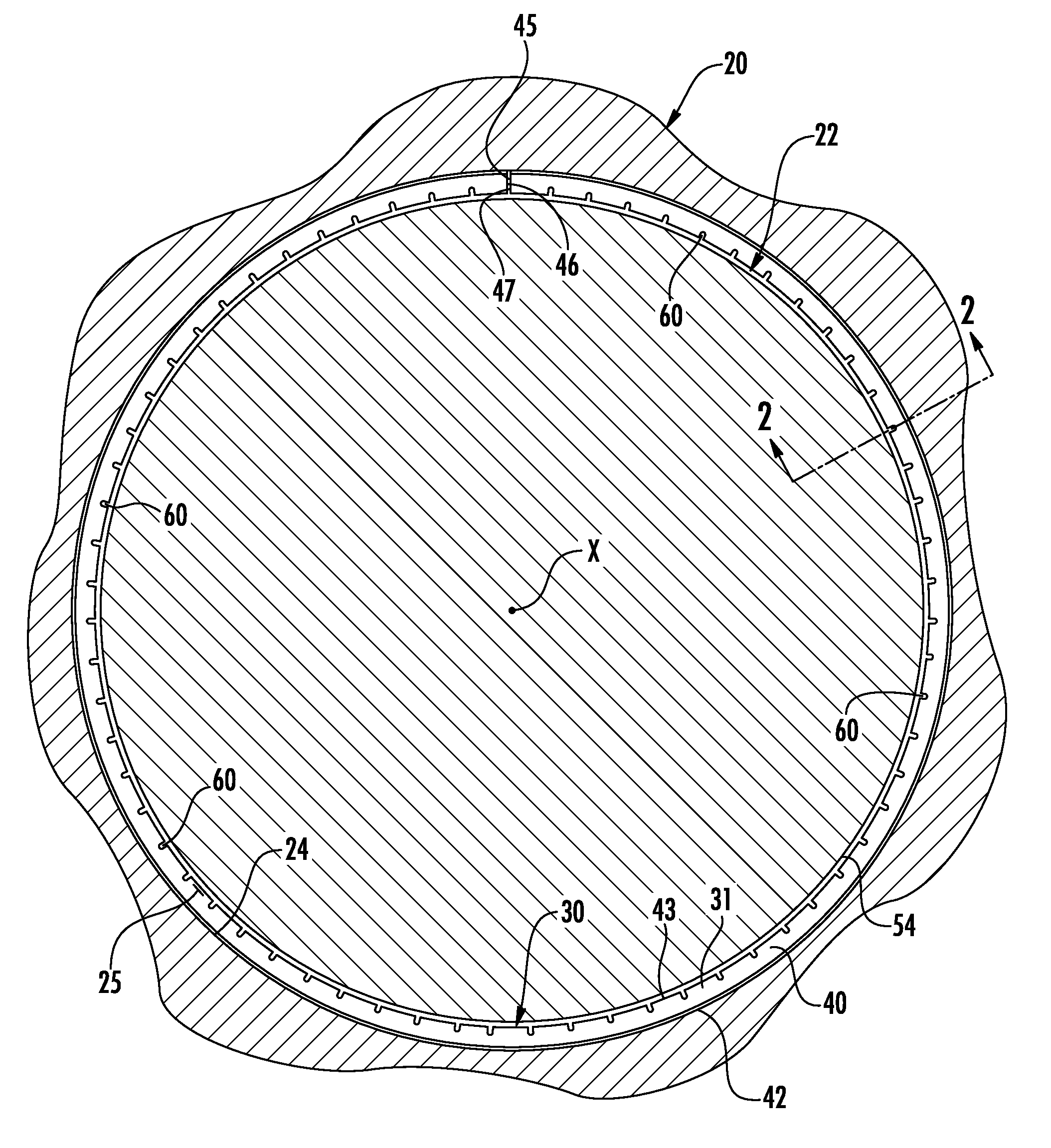
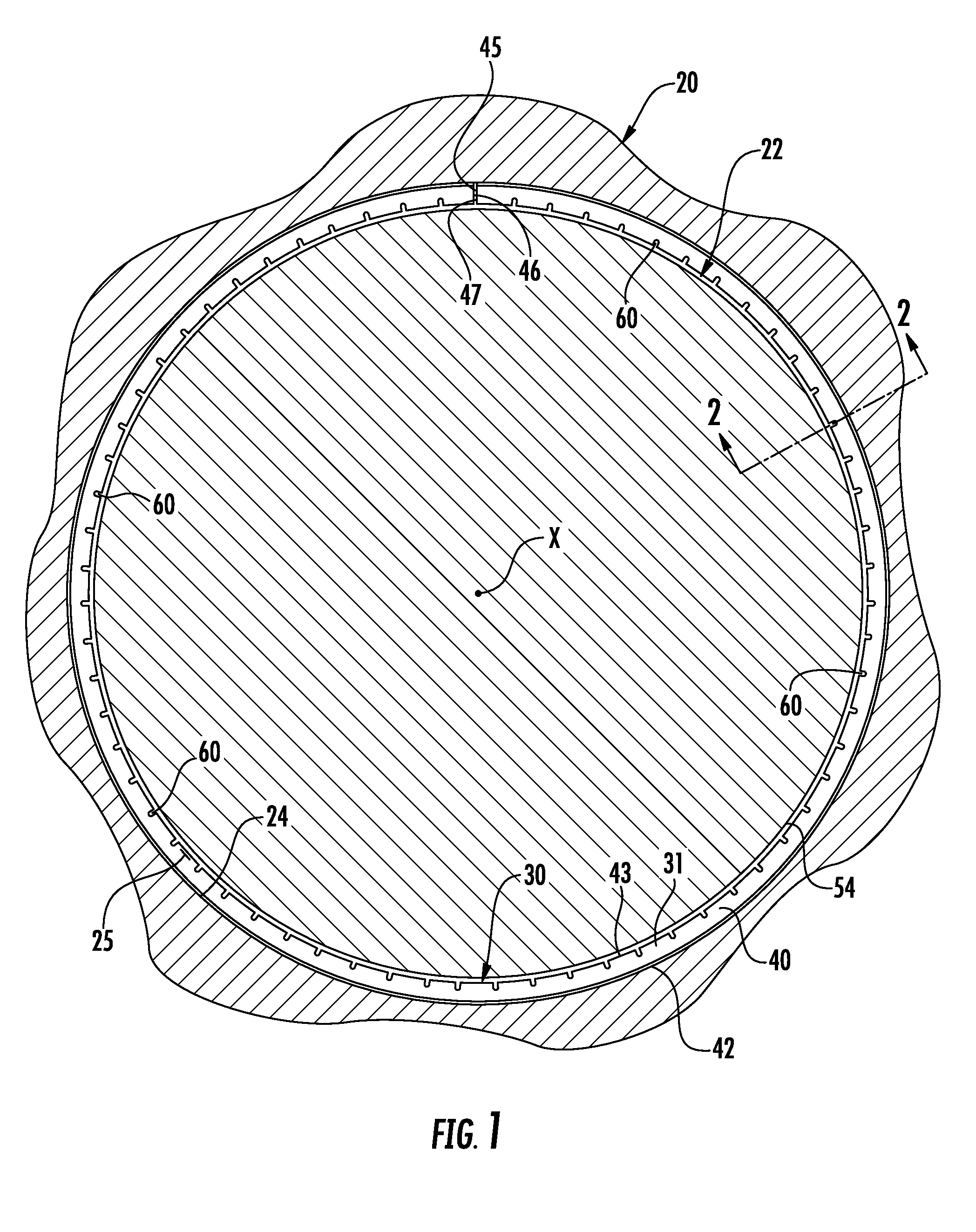
[0023]Turning now to the drawings, in which like reference characters indicate corresponding elements throughout the several views, attention is first directed to FIG. 1 which shows a mechanism including a first member, generally designated by the reference character 20, and a second member, generally designated by the reference character 22, which are disposed for relative reciprocal movement along a linear axis X which is perpendicular to the plane of the illustration. The mechanism is typically representative of internal combustion engines, positive displacement pumps, linear fluid actuated motors and similar apparatus in which first member 20 is generally referred to as the bore or cylinder and second member 22 is usually referred to as the piston. In FIG. 2, first member 20 includes inner cylindrical sidewall 23 which is coaxial with and spaced from outer cylindrical sidewall 24, also shown in FIG. 1, of second member 22. The space, commonly termed sidewall clearance and herein...


PUM


Abstract

In an annular groove carried by one of a pair of reciprocally movable members, a piston ring is carried by the annular groove for sealing the reciprocally movable members for minimizing fluid leakage between the members. The piston ring is an annular member that includes an outer contact surface engagable with the sidewall, an opposed inner surface, an end gap that severs the annular member and that defines spaced-apart first and second ends of the annular member, and annular member tension-relieving notches formed in the inner surface of the annular member. The notches are spaced-apart along the length of the annular member between the first end and the second end, and each notch has a blunt notch tip for inhibiting crack propagation in the annular member from said blunt notch tip when the annular member is tensioned.

Description

FIELD OF THE INVENTION[0001]This invention concerns seals and, more particularly, annular seals of a type for minimizing fluid leakage between reciprocally movable members, particularly a piston and a cylinder assembly, and for reducing emissions, improving fuel economy, and decreasing oil consumption in internal combustion engines.BACKGROUND OF THE INVENTION[0002]Various mechanical apparatus include first and second members, which are substantially coaxial and disposed for relative reciprocal movement. Exemplary are internal combustion engines, positive displacement pumps, pneumatic motors and other mechanical devices incorporating a piston and a cylinder assembly. Other examples will occur to the skilled artisan.[0003]Commonly, the cylinder is defined by a bore having a cylindrical sidewall. The piston, a generally cylindrical member, includes a sidewall and a top. An end wall or head, opposing the top of the piston, closes one end of the bore. A chamber of variable capacity is de...

Claims


Application Information

Patent Timeline
IPC IPC(8): F16J9/12F16J9/26
CPCF16J9/26F16J9/12F16J9/20
Inventor HARTFORD, MATTHEWMORIARTY, JOSEPH D.JOHNSON, KURT W.
Owner TOTAL SEAL
Why Eureka
Try Eureka