Fluid conveyance device

a technology of fluid conveyancing and fluid, which is applied in the direction of positive displacement liquid engines, electric/electrostrictive/magnetostrictive devices, pumps, etc., can solve the problems of difficult implementation of the mechanism for conveying a miniature volume pocket holding fluid, difficulty in forming elastically deformable joints connecting piezoelectric elements, and bulky and complex pump structure. , to achieve the effect of simple and compact structur

Active Publication Date: 2011-09-22
MURATA MFG CO LTD
View PDF3 Cites 4 Cited by
  • Summary
  • Abstract
  • Description
  • Claims
  • Application Information

AI Technical Summary

Benefits of technology

[0009]To overcome the problems described above, preferred embodiments of the present invention provide a simple and compact structure for a fluid conveyance device which efficiently conveys a fluid.
[0011]In accordance with a preferred embodiment of the present invention, the disk-shaped piezoelectric element includes the plurality of circular or substantially circular concentric segment electrodes arranged on the substrate. The substrate and the piezoelectric element are preferably in contact with substantially no gap therebetween when no voltage is applied to the piezoelectric element. When voltages having the same or substantially the same amplitude and shifted in phase are applied to the segment electrodes, a wavy ring deformation occurs on the piezoelectric element. The wavy ring deformation produces a ring pocket between the piezoelectric element and the substrate. The ring pocket moves in a radial direction from the outer substantially circular portion to the inner substantially circular portion or from the inner substantially circular portion to the outer substantially circular portion, thereby conveying the fluid between the outer substantially circular portion and the central portion. Since the ring pocket holding the fluid is sealed by the piezoelectric element itself, leakage of the fluid is minimized. The fluid within the pocket is steadily conveyed, and a high ejection pressure is generated. Since the piezoelectric element has a disk shape including the concentric segment electrodes, a simple and compact structure is achieved.
[0012]The fluid conveyed by the fluid conveyance device according to a preferred embodiment of the present invention may preferably be a liquid or a gas (such as air). In particular, if the piezoelectric element is driven at a high frequency, the fluid is preferably a gas. When air is used as the fluid, the fluid conveyance device may preferably be used as a cooling blower for semiconductor devices or a blower for evaporating water generated at an air electrode of a fuel cell. The amplitudes of the voltages applied to the segment electrodes need not necessarily be equal or substantially equal at all of the segment electrodes. However, if the amplitudes of the voltages are set to be equal or substantially equal to each other, the amount of displacement of each of the segment electrodes is set to be substantially equal. If the gaps between the segment electrodes are radially arranged with an equal or substantially equal pitch, the volume of the pocket is changed at a substantially constant rate, and the flow of the fluid is smooth.
[0016]In a structure supporting the piezoelectric element on the substrate, the outer substantially circular portion of the piezoelectric element may preferably be fixed to the substrate or may preferably be elastically supported by the substrate. In the former case, the outer substantially circular portion of the piezoelectric element is preferably fixed to the substrate, and the piezoelectric element is prevented from lifting off of the substrate. The efficiency of the pump is increased. In the latter case, the outer substantially circular portion of the piezoelectric element is bent, which causes a second flow passage port between the piezoelectric element and the substrate. The piezoelectric element is not strongly bound and is thus free to be displaced. Any optional support structure may be applied to the piezoelectric element.
[0017]The piezoelectric element is preferably a multilayer type having a bimorph structure. For example, the piezoelectric element may be a multilayer type in which at least three circular or substantially circular concentric segment electrodes and a full-surface nonsegmented electrode are alternately laminated with a piezoelectric layer interposed therebetween. The piezoelectric element may preferably be a multilayer type in which a plurality of first substantially circular concentric segment electrodes and a plurality of second segment electrodes are alternately laminated with a piezoelectric layer interposed therebetween, and wherein the second segment electrodes are concentric with the first segment electrodes and gaps between the second segment electrodes are alternately arranged with a gap between the first segment electrodes in a radial direction. In the former case, one electrode is a full-surface electrode, and each of the electrode patterns are the same type. The latter case provides the advantage that the number of segment electrodes on a surface is less than that of the former case, and that the voltage applied to each segment electrode can be reduced.
[0021]In accordance with a preferred embodiment of the present invention, the disk-shaped piezoelectric element including the plurality of substantially circular concentric segment electrodes is arranged on the substrate. The voltages are applied to the segment electrodes with the phase of the voltages being successively shifted. Thus, the piezoelectric element is bent, which produces the ring pocket between the piezoelectric element and the substrate. By moving the pocket in a radial direction, the fluid is radially conveyed. Since the piezoelectric element has a disk shape, and the segment electrodes are concentric or substantially concentric, the ring pocket holding the fluid is sealed with the piezoelectric element itself, and a high ejection pressure is produced. Since the fluid conveyance device includes the single disk-shaped piezoelectric element and the substrate, the device can be simple, compact, and thin. Furthermore, since the flow passage between the inlet port and the outlet port is closed by the bent piezoelectric element, check valves are not required for the inlet port and the outlet port.

Problems solved by technology

Since the plurality of piezoelectric elements are arranged in a plane, the pump has a bulky and complex structure.
Since the plurality of piezoelectric elements operate in a tube-pump mode, the structure of an elastically deformable joint connecting the piezoelectric elements and sealing of the fluid presents difficulties.
A mechanism for conveying a miniature volume pocket holding the fluid is also difficult to implement.
As in the above-described related art, a plurality of electrodes must be arranged in the direction of motion, and the pump has a bulky structure.
Sealing of a joint connecting the elastically deformable electrodes is also difficult.
A miniature volume pocket containing the fluid is also difficult to convey.

Method used


Image

  • Fluid conveyance device
  • Fluid conveyance device
  • Fluid conveyance device

Examples


first preferred embodiment

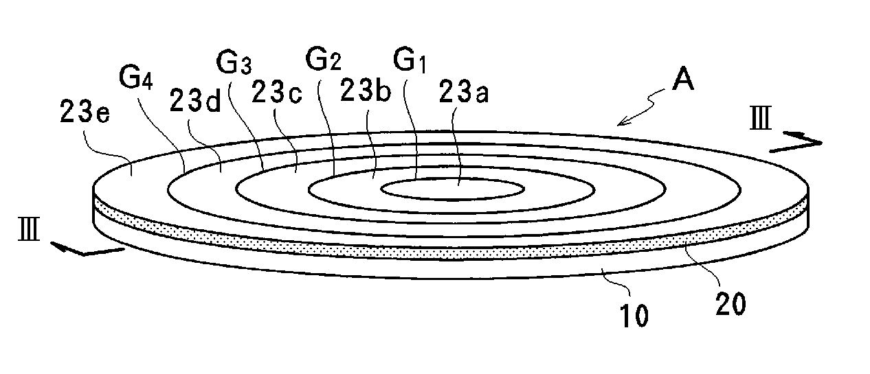
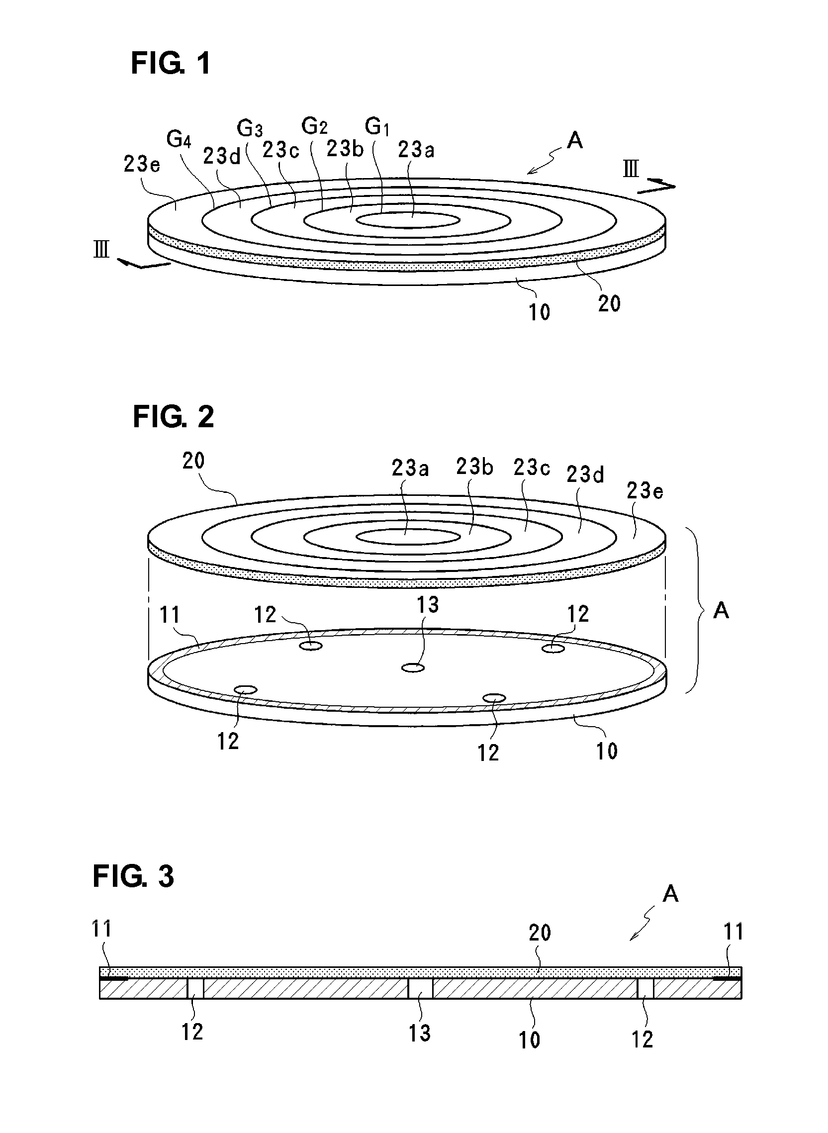
[0046]FIGS. 1-3 illustrate a first preferred embodiment of a fluid conveyance device of the present invention. Here, the fluid conveyance device is preferably used as an air supplying micro pump. FIG. 1 is a perspective view of the micro pump A of the first preferred embodiment, FIG. 2 is an exploded perspective view of the micro pump A, and FIG. 3 is a sectional view taken along line III-III in FIG. 1.

[0047]The micro pump A of the first preferred embodiment includes a substrate 10 defining a fixed plate, and a disk-shaped piezoelectric element 20 arranged in a bendable manner on the substrate 10. An entire or substantially entire outer substantially circular portion of the piezoelectric element 20 is preferably bonded to the piezoelectric element 20 preferably by an adhesive agent 11, for example. In accordance with the first preferred embodiment, the substrate 10 and the piezoelectric element 20 are preferably disks having the same or substantially the same diameter, for example. ...

second preferred embodiment

[0058]FIGS. 12A-14 illustrates a second preferred embodiment of a fluid conveyance device of the present invention. Unlike the first preferred embodiment, the second preferred embodiment includes two different patterns as the segment electrodes of a piezoelectric element 30. With the diameter of the piezoelectric element 30 being 5D, a first electrode pattern includes three concentric substantially circular segment electrodes 32a-32c divided along a diameter D and a diameter 3D as illustrated in FIG. 12A, and a second electrode pattern includes three concentric substantially circular segment electrodes 33a-33c divided along a diameter 2D and a diameter 4D as illustrated in FIG. 12B.

[0059]As illustrated in FIG. 13, two types of segment electrodes 32a-32c and 33a-33c are preferably laminated with piezoelectric layers 31a and 31b interposed therebetween. The segment electrodes 32a at the approximate center are mutually connected to the outermost segment electrodes 32c, and the segment ...

third preferred embodiment

[0063]FIGS. 17-19 illustrate a third preferred embodiment of the fluid conveyance device of the present invention. In accordance with the third preferred embodiment, the electrode patterns of a piezoelectric element 40 are not concentric, but are arranged in a deviated arrangement as illustrated in FIG. 17. More specifically, ring segment electrodes 41b-41e are successively arranged around a central segment electrode 41a in an arrangement that is not centered. A pitch of the gaps G4-G4 defining border lines between the segment electrodes is set to substantially proportional to the square root of a distance to an imaginary straight line O, shown in FIG. 19, outside the piezoelectric element 40. In this preferred embodiment, the imaginary straight line O is x=0 (Y axis in FIG. 18). The border line pitch is preferably set to be about 0.8x0.5, for example, so that the pitch is substantially proportional to the square root of a distance x from the imaginary straight line O. If the diamet...


PUM


Abstract

A fluid conveyance device includes a substrate, and a disk-shaped piezoelectric element arranged in a bendable manner on the substrate. A plurality of substantially circular concentric segment electrodes are provided on the piezoelectric element, and are provided with voltages with phases that are shifted. A wavy ring deformation is thus produced on the piezoelectric element. A pocket produced between the piezoelectric element and the substrate is moved in a radial direction so as to convey a fluid from an outer substantially circular portion to a central portion and to discharge the fluid from the central portion.

Description

BACKGROUND OF THE INVENTION[0001]1. Field of the Invention[0002]The present invention relates to fluid conveyance devices and, in particular, to a fluid conveyance device utilizing a bending piezoelectric element.[0003]2. Description of the Related Art[0004]A piezoelectric pump has been used as a coolant water pump for a compact electronic apparatus, such as a notebook personal computer, and a fuel transport pump for a fuel cell, for example. The piezoelectric pump is also used as a fan pump which replaces a cooling fan for a CPU or other electronic apparatus, or a fan pump for supplying oxygen required by a fuel cell that generates power. The piezoelectric pump is a pump that utilizes a piezoelectric element that bends into a shape thereof in response to voltage application. The advantages of the piezoelectric pump are a simple and thin structure and low power consumption.[0005]Japanese Unexamined Patent Application Publication No. 2-149778 and Japanese Unexamined Patent Applicatio...

Claims


Application Information

Patent Timeline
Patent Type & Authority Applications(United States)
IPC IPC(8): F04B17/00
CPCF04B43/046H01L41/0973H01L41/0833H01L41/0471H10N30/871H10N30/503H10N30/2047
Inventor KAMITANI, GAKUHIRATA, ATSUHIKO
Owner MURATA MFG CO LTD
Why Eureka
Try Eureka