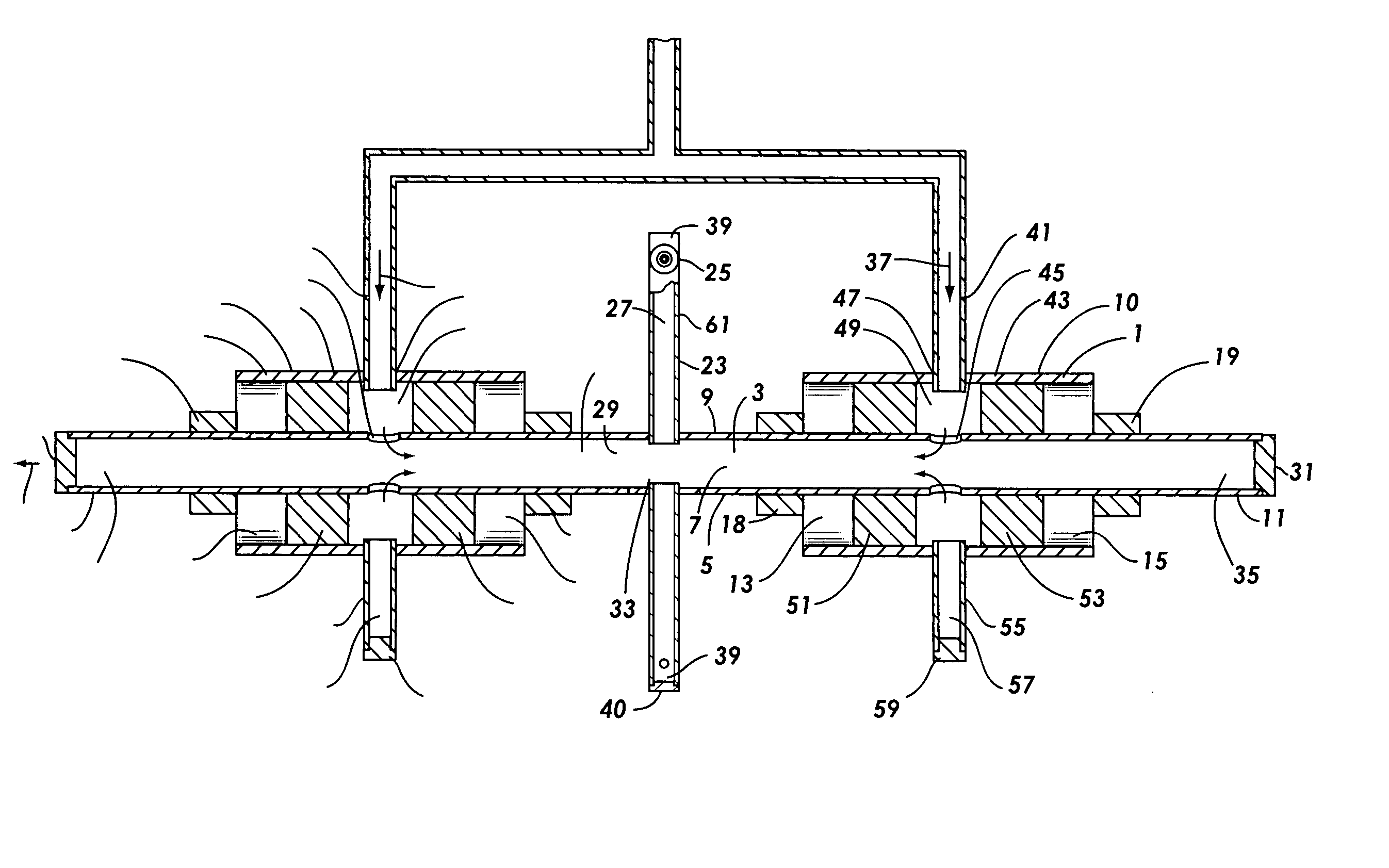
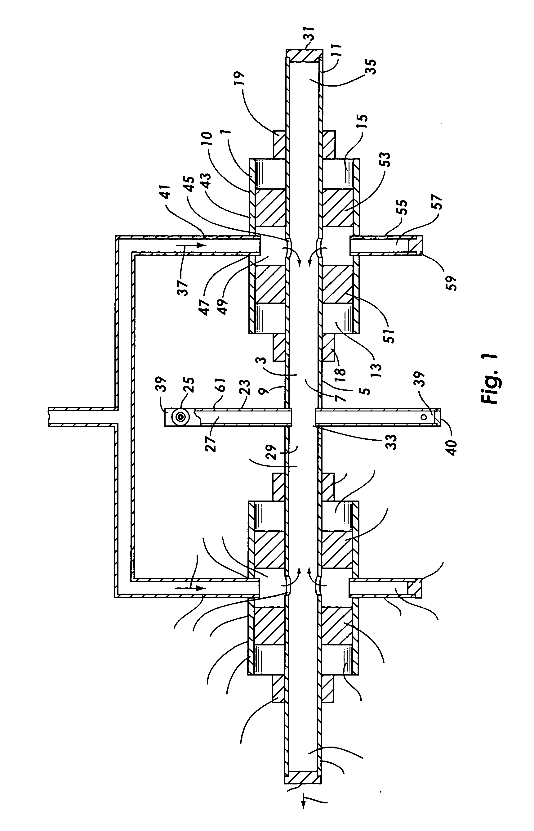
[0015] The pressurized fluid bladeless turbine engine of the present invention has a pair of opposing intake assemblies which are positioned on opposing sides of the turbine. Each intake
assembly incorporates a shaft with an internal shaft fluid way or one or more
peripheral shaft fluid ways. The
peripheral shaft ways may be concentric shaft fluid ways affixed to a shaft core or longitudinal, segmental shaft fluid ways in a circumferential conduit which is affixed to a shaft core. Lateral fluid intakes provide for pressurized fluid to be fed to the shaft fluid ways from one or more pressurized fluid sources. Each pressurized fluid intake
assembly allows for the lateral intake of pressurized fluid to the shaft while not interfering with
power take off from the shaft.
Power take off-can occur on either side of the turbine. Each pressurized fluid intake assembly includes shaft seals which minimize pressurized
fluid leakage and shaft bearings which provide for the
free rotation of the shaft and the turbine. The shaft, intake, seal and bearing components and configuration of the present invention provide for low cost fabrication. Low tolerance
machining and high cost materials are minimized for this engine.
[0017] The bladeless turbine has two or more
nozzle arms affixed to the shaft and the shaft fluid way is hydraulically connected to each
nozzle by
nozzle fluid ways. Shaft flash chambers and nozzle flash chambers provide for flashing control for a liquid pressurized drive fluid, to minimize undesirable flashing. A fluid supply line, which supplies the pressurized drive fluid, is affixed to the outer housing and hydraulically connected to the outer housing of each intake assembly by a outer housing fluid intake. A front shaft seal and a rear shaft seal allow the rotation of the shaft in the inner housing of each intake assembly while preventing leakage of the drive fluid along the shaft. This embodiment of the turbine engine of the present invention is adaptable to known and readily available shaft seals. Embodiments having an internal shaft fluid way will accommodate pressurized fluid from multiple gas sources, all of which can be input by a
pipe affixed to fluid intakes in the outer housing. However, these embodiments do not provide for respective pairs or sets of nozzles to utilize pressurized fluid from different gas sources.
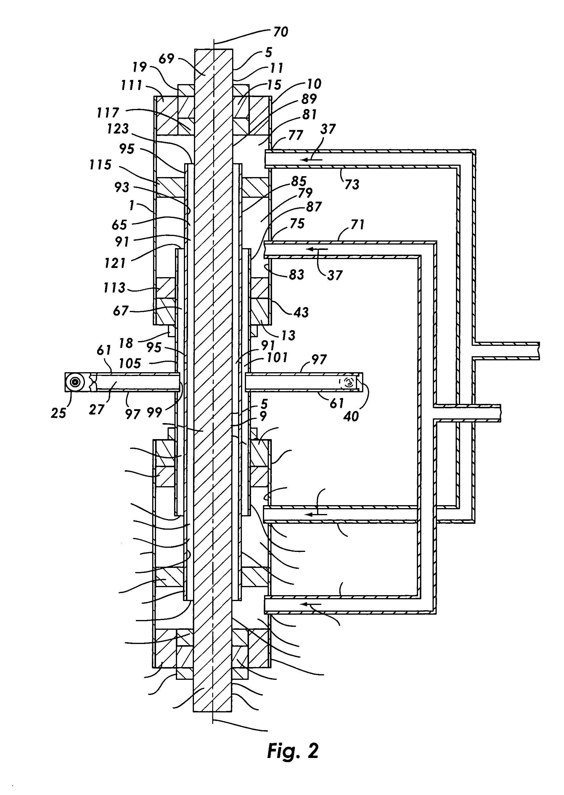
[0018] Embodiments having two or more
peripheral, concentric shaft fluid ways provide for conveying the drive fluid independently to pairs or sets of nozzle arms. An inner shaft fluid way is affixed to the shaft core. Additional shaft fluid ways are affixed concentrically to the shaft. Each nozzle fluid way is hydraulically connected to a concentric shaft fluid way. The concentric shaft fluid ways make it possible to utilize a
solid shaft core, thereby increasing the strength and durability of the shaft. This embodiment also provides for
power take off from a front
power take off or a rear power take off, or both.
[0021] Shaft seals are required for each intake assembly, the number depending on the number of fluid supply chambers required, to minimize leakage of the drive fluid from the supply chambers. Embodiments providing for the independent input of additional fluid sources merely require additional concentric shaft fluid ways and additional fluid supply chambers separated by a respective inner seal. Also, depending upon the length and other physical characteristics of the shaft, multiple shaft fluid way embodiments may require additional inner bearings. A plurality of pressurized fluid supply lines and a plurality of pressurized fluid sources can be connected to any or all of the fluid supply chambers.
[0023] Other preferred embodiments may incorporate a circumferential conduit which is attached to a shaft core. The circumferential conduit is divided into two or more contiguous, longitudinal, segmental shaft fluid ways which intake pressurized fluid from the respective pressurized fluid sources through fluid way intakes which are isolated in respective circumferential supply chambers by respective shaft seals. A front shaft bearing and a rear shaft bearing bear between the outer housing and the circumferential conduit providing for the
free rotation of the shaft in the outer housing. The circumferential conduit and the shaft fluid ways extend rearward from the rear shaft bearing and the outer housing rear wall. Thrust plugs in each of the shaft fluid ways provide for reducing the thrust imposed on the bearings.
[0025] For the preferred embodiments and any variations thereof, any support structure for the turbine engine can be affixed to the outer housing. The entire turbine engine of these embodiments can be enclosed in a turbine engine body for fluid capture and recycle and for
waste heat capture and recycle. Alternatively, the turbine can be enclosed in a turbine engine body with the turbine shaft extending through one wall of the turbine engine body, thereby allowing for fluid and
waste heat capture and recycle.
