Method and System for Equalization and Decoding Received Signals Based on High-Order Statistics in Optical Communication Networks

a technology of optical communication network and received signal, applied in the field of communication network, can solve the problems of nonlinear impairment, affecting the performance of coherent optical transmission system, low bandwidth efficiency, etc., and achieve the effect of improving the performance of the receiver

Inactive Publication Date: 2013-07-04
MITSUBISHI ELECTRIC RES LAB INC
View PDF31 Cites 16 Cited by
  • Summary
  • Abstract
  • Description
  • Claims
  • Application Information

AI Technical Summary

Benefits of technology

The patent text describes a new form of equalizer called a sliding window MAP equalizer that is combined with a decoder to form a Turbo Equalization (TEQ) structure in the receiver. This new equalizer is simpler and more efficient than previous methods, and can be used in conjunction with other equalization techniques to improve the performance of the receiver.

Problems solved by technology

The main drawback of intensity signalling is that bandwidth efficiency is low, due to the fact that data are transmitted only in a single dimension, i.e., signal intensity.
Several impairments affect the performance of such coherent optical transmission systems.
Nonlinear impairments have become a major limiting factor for high-rate data transmissions in long-haul optical fiber channels.
However, the DBP suffers from high complexity in implementations and has reduced effectiveness in the presence of Amplified Spontaneous Emission (ASE) noise in optical amplifiers.
Nevertheless, performance and implementation complexity remain a challenge.
Significant performance improvements have been obtained in simulations, but the complexity is too high to be realistically implemented in high-rate applications, such fiber-optic communications.
Such system uses only the first-order statistics (mean values), and therefore offers limited performance improvement.

Method used


Image

  • Method and System for Equalization and Decoding Received Signals Based on High-Order Statistics in Optical Communication Networks
  • Method and System for Equalization and Decoding Received Signals Based on High-Order Statistics in Optical Communication Networks
  • Method and System for Equalization and Decoding Received Signals Based on High-Order Statistics in Optical Communication Networks

Examples


Embodiment Construction

[0028]Coherent Fiber-Optic Network

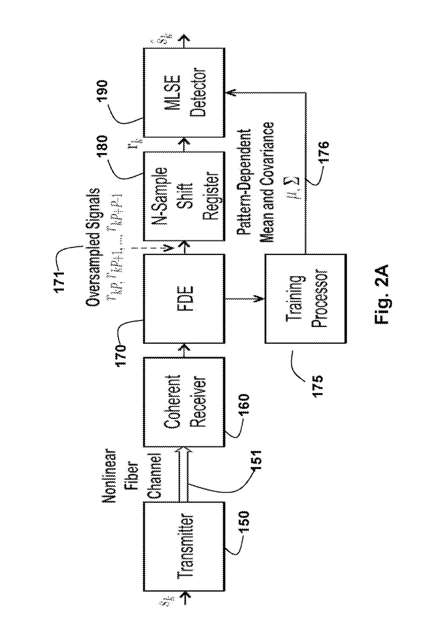
[0029]FIG. 2A shows a coherent fiber-optic network with a fractionally-spaced statistical sequence equalizer according to embodiments of our invention.

[0030]A transmitter 150 transmits symbols sk via a nonlinear fiber optical channel 151 to a coherent receiver 160. After digitizing to, e.g., two samples per symbol, residual dispersion is removed using linear frequency-domain equalizer (FDE) 170. The oversampling signal is fed into a shift register 180 to obtain subsequences, and then a statistical Maximum-Likelihood Sequence Estimator (MLSE) equalizer 190 to determine an estimate of the transmitted signal. The MLSE detector 190 uses channel statistics 176, learned by a training processor 175. The channel statistics include high-order statistics, such as mean, covariance, skewness and kurtosis.

[0031]The invention is based on the realization that nonlinear distortion highly depends on patterns in the transmitted signal. Therefore, the statistical sequ...


PUM


Abstract

A method equalizes and decodes a received signal including a sequence of symbols. Subsequences of the signal are selected, wherein the subsequences are overlapping and time shifted. For each subsequence, statistics of the channel corresponding to a pattern in the subsequence are selected, wherein the statistics include high-order statistics. A transmitted signal corresponding to the received signal is then estimated based on the statistics.

Description

FIELD OF THE INVENTION [0001]This invention relates generally to communication networks, and more particularly to equalizing and decoding coherently received optical signals.BACKGROUND OF THE INVENTION[0002]A desire to increase the data rate and transmission distance of communication channels has driven engineers and designers to consider the use of coherent signal transmissions, e.g., in optical networks. Conventionally, optical communication networks have relied on the use of simple signalling methods to encode data bits onto an optical carrier.[0003]The most common signalling method is intensity modulation, in which a laser is gated to allow high intensity light to enter a fiber optical cable when a ‘1’ bit is transmitted, and low intensity light when a ‘0’ bit is transmitted. This is called on-off keying. This signalling method has the advantage that it is easily demodulated by a simple detector including a photodetector (typically a photo-diode) and an appropitate threshold.[00...

Claims


Application Information

Patent Timeline
Patent Type & Authority Applications(United States)
IPC IPC(8): H04B10/06
CPCH04L25/03171H04L25/03286H04L25/03184
Inventor KOIKE-AKINO, TOSHIAKIDUAN, CHUNJIEPARSONS, KIERANKOJIMA, KEISUKE
Owner MITSUBISHI ELECTRIC RES LAB INC
Why Eureka
Try Eureka