
Half Metal Trilayer TMR Reader with Negative Interlayer Coupling

a trilayer reader and negative interlayer coupling technology, applied in the field of trilayer magnetoresistive sensor, can solve the problems of track erasure and data loss, and the inability to have a playback head length less than 20 nm, and achieve high recording densities, high recording densities, and high recording densities.

Active Publication Date: 2013-06-27
WESTERN DIGITAL TECH INC
View PDF21 Cites 15 Cited by
  • Summary
  • Abstract
  • Description
  • Claims
  • Application Information

AI Technical Summary

Benefits of technology

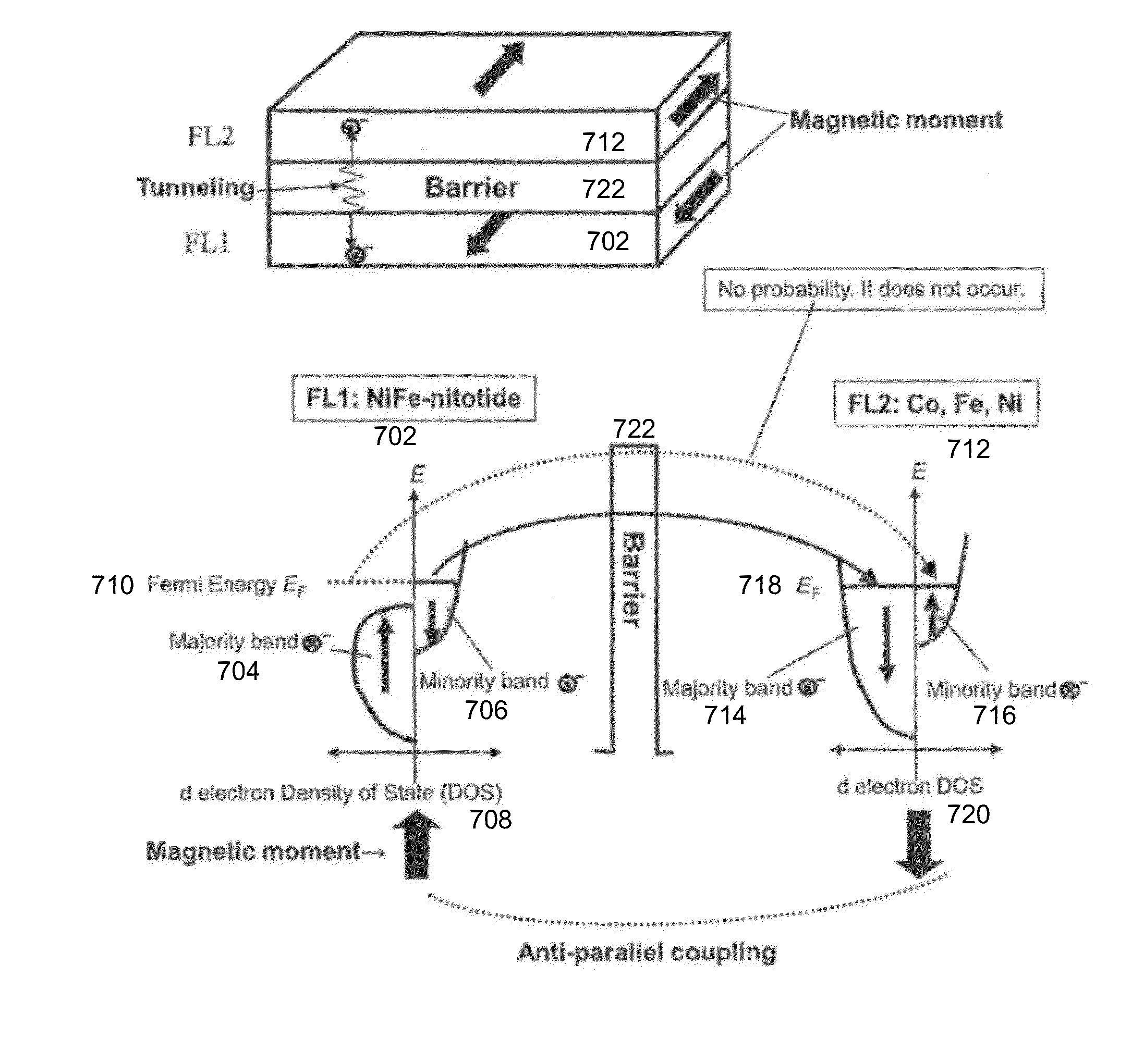
The invention relates to a trilayer magnetoresistive sensor that allows for high levels of recording densities. It includes a first free layer, a barrier layer, and a second free layer, which are deposited on an underlayer. The first free layer includes a nitride of an element including at least one of Fe, Co, or Ni, or a multiple laminate structure of a layer containing a nitride of an element including at least one of Fe, Co, or Ni, and a ferromagnetic layer containing at least one of Fe, Co, or Ni. The second free layer is an alloy ferromagnetic layer containing at least one element of Fe, Co, or Ni, or a multiple laminate structure with a different composition of an alloy ferromagnetic layer containing at least one of Fe, Co, or Ni and another ferromagnetic layer containing at least one of Fe, Co, or Ni. In both embodiments, the first and second free layers cause anti-parallel coupling, which allows for a thinner sensor that can achieve higher recording densities.

Problems solved by technology

A side effect of these single domain state designs is that, without closure domains, magnetic charge forms at the edge of the shield that can cause track erasure and loss of data.
Because currently used sensor films have an approximate minimum thickness of 20 nm, it is not possible to have a playback head length of less than 20 nm.

Method used


Image

  • Half Metal Trilayer TMR Reader with Negative Interlayer Coupling
  • Half Metal Trilayer TMR Reader with Negative Interlayer Coupling
  • Half Metal Trilayer TMR Reader with Negative Interlayer Coupling

Examples


first exemplary embodiment

[0059]In an embodiment of the invention as shown in FIG. 6, a trilayer magnetoresistive sensor 600 comprises an underlayer 602 on which a first free layer 608 is deposited. A barrier layer 616 is then deposited after which a second free layer 618 is deposited. A capping layer 626 is then deposited above second free layer 618.

[0060]The first free layer 608 is a layer which includes at least a layer 610 of a nitride of an element including at least one of Fe, Co, or Ni, or a multiple laminate structure of a layer containing a nitride of an element including at least one of Fe, Co, Ni and another ferromagnetic layer containing at least one of Fe, Co, or Ni. In an embodiment, second free layer 618 is an alloy ferromagnetic layer containing at least one element of Fe, Co and Ni, or a multiple laminate structure with a different composition of an alloy ferromagnetic layer containing at least one element of Fe, Co, and Ni.

[0061]The combination of first and second free layers 608 and 618 ca...

second exemplary embodiment

[0075]In another embodiment of the invention as shown in FIG. 9, a trilayer magnetoresistive sensor 900 comprising an underlayer 902 on which first free layer 908 is formed. Barrier layer 916 is formed on first free layer 908, and second free layer 918 is formed on barrier layer 916. Capping layer 928 is then formed above second free layer 918.

[0076]First free layer 908 or the second free layer 918 includes a nitride of an element including at least one of Fe, Co, or Ni, or a multiple laminate structure of a layer containing a nitride of an element including at least one of Fe, Co, or Ni and another ferromagnetic layer containing at least one of Fe, Co, or Ni. The other free layer is preferably a Heusler ferromagnetic layer or a multiple laminate structure with a different composition of a Heusler ferromagnetic layer and an alloy ferromagnetic layer containing at least one element of Fe, Co, or Ni, thus causing anti-parallel coupling (i.e., J908 and 918, respectively.

[0077]To be des...

third exemplary embodiment

[0087]Another embodiment of the invention provides a trilayer magnetoresistive sensor 1100 as shown in FIG. 11. Trilayer magnetoresistive sensor 1100 comprises an underlayer 1102 with first free layer 1108 above. Barrier layer 1124 is formed over first free layer 1108. Second free layer 1126 is formed above barrier layer 1124. Cap layer 1134 is formed above second free layer 1126.

[0088]First free layer 1108 comprises first ferromagnetic layer (AP1) 1110, antiparallel coupling layer 1118, and second ferromagnetic layer (AP2) 1112 which is in below barrier layer 1124. With the magnetic moment of AP11110 and AP21112 in an anti-parallel slate, the magnetic moment of AP11110 is greater than the magnetic moment of AP21112. The second free layer 1126 comprises two ferromagnetic layers 1128 and 1132. Ferromagnetic layers 1128 and 1132 are ferromagnetic layers which include at least one element of Fe, Co or Ni, or a multiple laminate structure with a different composition of alloy ferromagne...


PUM

PropertyMeasurementUnit
heightaaaaaaaaaa
playback gap lengthaaaaaaaaaa

Abstract

In an embodiment of the invention, a trilayer magnetoresistive sensor comprises an underlayer on which a first free layer is deposited. A barrier layer is then deposited after which a second free layer is deposited. A capping layer is then deposited above second free layer. The first free layer is a layer which includes at least a layer of a nitride of an element including at least one of Fe, Co, or Ni, or a multiple laminate structure of a layer containing a nitride of an element including at least one of Fe, Co, Ni and another ferromagnetic layer containing at least one of Fe, Co, or Ni. The combination of the first and second free layers causes anti-parallel coupling.

Description

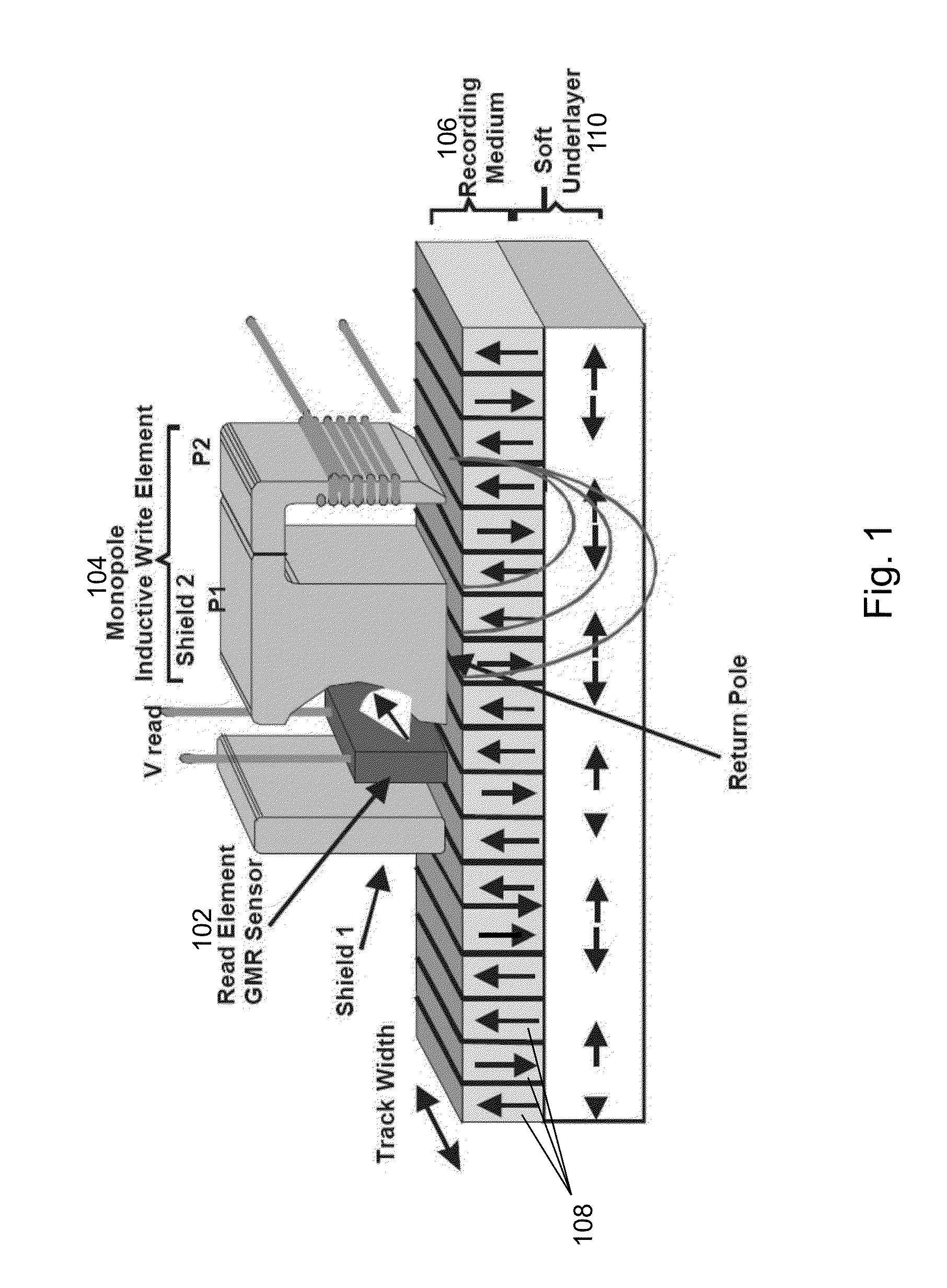
FIELD OF THE INVENTION[0001]The present invention generally relates to the field of computer hard disks. More particularly, the present invention relates to a trilayer magnetoresistive sensor and to a method for making a trilayer magnetoresistive sensor.BACKGROUND OF THE INVENTION[0002]A read / write head in a disc drive typically includes a magnetoresistive (MR) read transducer that is deposited between non-magnetic layers and magnetic shield layers. The magnetoresistive read transducer typically includes a magnetoresistor, electrical contacts and one or more bias magnets that magnetically bias the magnetoresistor. Various magnetic biasing arrangements in the magnetoresistive sensor can be used to improve uniformity, predictability, linearity, and / or reduce noise.[0003]Domains formed in the nearby magnetic shield layers can also magnetically bias the magnetoresistor. Control of both domain magnetization direction and domain wall location in the shields are important for the proper op...

Claims


Application Information

Patent Timeline
Patent Type & Authority Applications(United States)
IPC IPC(8): B32B15/04B32B9/00B05D5/12
CPCB82Y40/00B32B9/00B32B15/04H01L43/08H01L43/12G01R33/098H01F41/307G11B5/3163G11B5/3909G01R33/093H01F10/3272H10N50/10H10N50/01
Inventor NISHIOKA, KOICHI
Owner WESTERN DIGITAL TECH INC
Learn More