Method and apparatus for dual pass rate control video encoding

a dual-pass rate control and video encoding technology, applied in signal generators with optical-mechanical scanning, color televisions with bandwidth reduction, television systems, etc., can solve the problems of affecting video quality, complexity information always lags behind the actual encoding process, and the complexity of a frame or picture is not known until

Inactive Publication Date: 2013-06-20
GOOGLE TECH HLDG LLC
View PDF14 Cites 25 Cited by
  • Summary
  • Abstract
  • Description
  • Claims
  • Application Information

AI Technical Summary

Benefits of technology

This patent describes a method and system for dual-pass rate control video encoding. The system receives uncompressed video and performs two encoding passes through a video encoder. The first pass detects scene changes, assigns macroblocks to activity classes, and determines the complexity of each picture. The second pass uses information from the first pass to control the rate of the video, adjusting the boundaries of each group of pictures (GOP) to align with the scene changes. The technical effect is that the system allows for improved video quality and efficient use of codec resources for video encoding.

Problems solved by technology

Efficient transmission of video requires compression and formatting techniques to be utilized, for instance, due to bandwidth limitations.
This means the complexity of a frame or picture is not known until it has been encoded.
As a result, the complexity information always lags behind the actual encoding process, which requires the buffering of a number of frames prior to encoding.
With respect to scene changes, identifying a scene change at a cut and managing an abrupt change in video coding that may occur at a scene change boundary provide challenges and can impact video quality.
Here, the problem is to balance the need to avoid violating the model and yet still use the fullest possible extent of the buffer to ensure that video quality is maximized for a given bit rate.
However, the range of available quantizers may be small, for instance, limited to 52 values between zero (0) and 51 for the H.264 / MPEG-4 standard.
Thus, a small change in selected quantizer value can result in a large change in number of bits coded.
However, in practice, the percent change can be quite variable and, when increasing or decreasing the quantizer value by greater than one (1), the percent bit change may not be accurately predicted because the percentages tend not to scale well.
Accordingly, the ability to accurately predict the number of bits produced via use of a quantizer value can be difficult.

Method used


Image

  • Method and apparatus for dual pass rate control video encoding
  • Method and apparatus for dual pass rate control video encoding
  • Method and apparatus for dual pass rate control video encoding

Examples


Embodiment Construction

[0019]For simplicity and illustrative purposes, the principles of the embodiments are described by referring mainly to examples thereof. In the following description, numerous specific details are set forth in order to provide a thorough understanding of the embodiments. It will be apparent however, to one of ordinary skill in the art, that the embodiments may be practiced without limitation to these specific details. In some instances, well known methods and structures have not been described in detail so as not to unnecessarily obscure the embodiments.

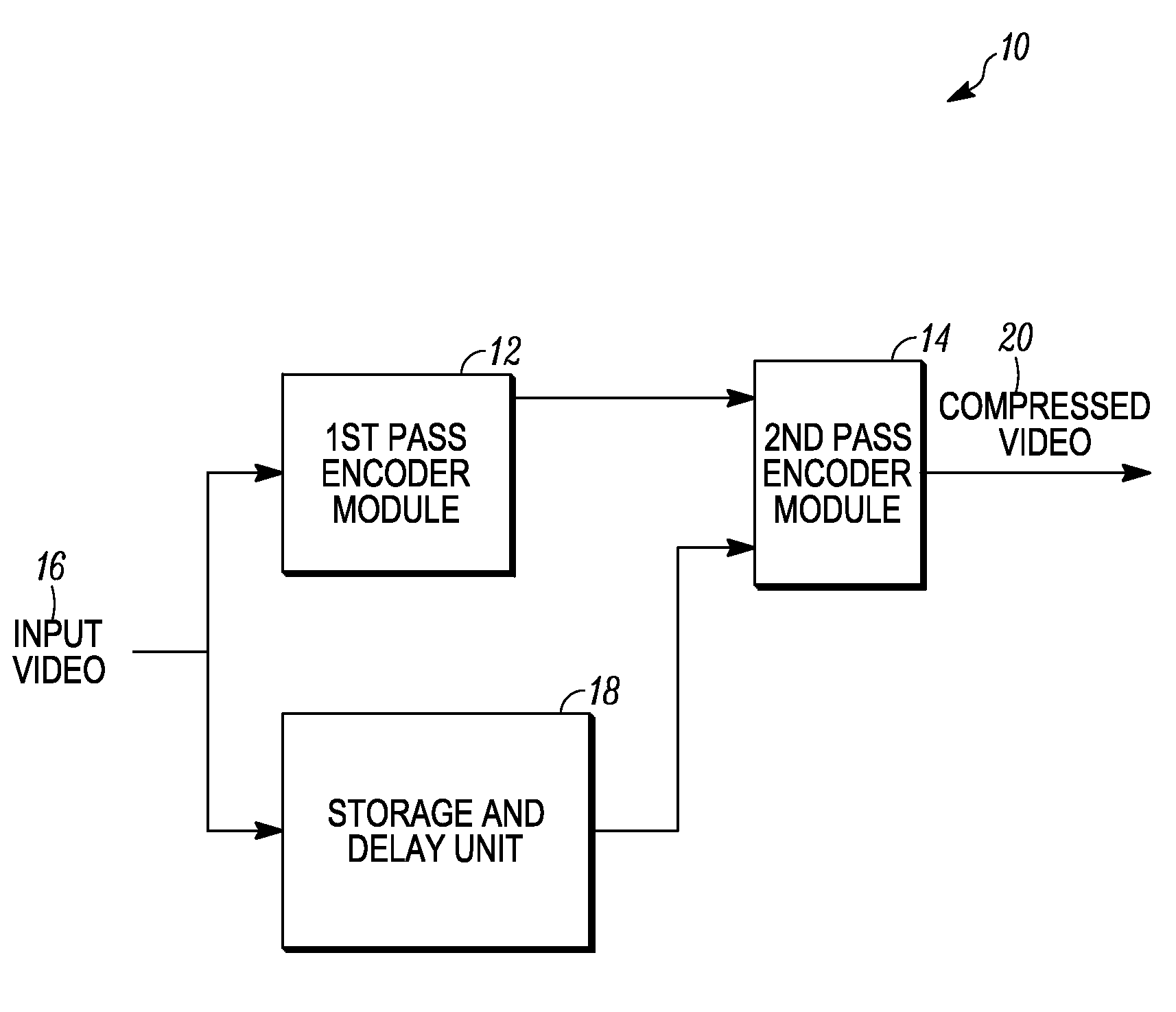
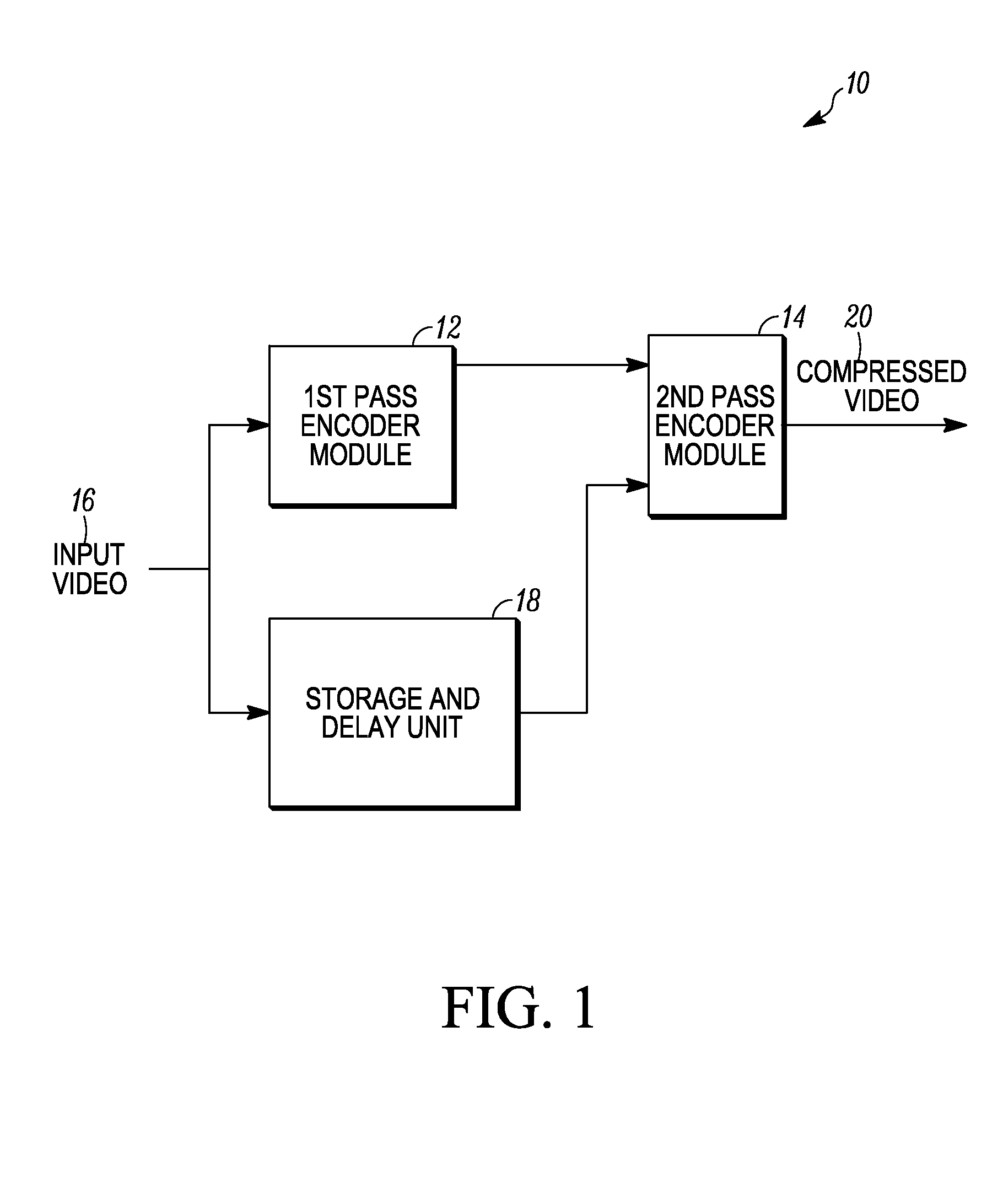
[0020]FIG. 1 illustrates a block diagram of a two-pass MPEG encoder 10 having a first pass encoder module 12 and a second pass encoder module 14 receiving the same input video sequence 16. The input video sequence 16 passes through a storage and delay unit 18 before being input into the second pass encoder module 14 to provide a delay between first encoding pass in the first pass encoder module 12 and second encoding pass in the seco...


PUM


Abstract

A method of dual-pass rate control video encoding and an encoder are disclosed. Uncompressed input video is received with a video encoder. First pass encoding is performed, and a second pass encoding is performed with the video encoder at a delay relative to the first pass. The first pass encoding detects scene changes within the input video, assigns macroblocks to a pre-determined number of activity classes, and determines a complexity of each picture within the sequence of pictures. Information from the first pass encoding concerning the scene changes, the activity classes, and the complexity are used for rate control determined in second pass encoding for producing and outputting a bit stream of compressed video. During at least one of the first pass and second pass encoding, boundaries of at least some of the GOPs are adjusted to be aligned with the scene changes.

Description

FIELD[0001]Method and apparatus for dual-pass rate-control video encoding are described.BACKGROUND[0002]Video images in an information stream can be transmitted to a user via a broadband communication network, for instance, over a satellite, cable, or terrestrial transmission medium. Efficient transmission of video requires compression and formatting techniques to be utilized, for instance, due to bandwidth limitations. Various protocols, such as MPEG protocols, have been designed to maximize bandwidth utilization for video information transmission by adding a temporal component to a spatial compression algorithm.[0003]Each individual image or picture in a sequence of images or pictures of video can be referred to as a frame or field. Each picture or frame is made up of a large number of picture elements (pixels) that define the image. Within each picture or frame, redundant pixels describe like parts of a scene, e.g. a blue sky. Various types of compression algorithms have been use...

Claims


Application Information

Patent Timeline
Patent Type & Authority Applications(United States)
IPC IPC(8): H04N7/26
CPCH04N19/172H04N19/15H04N19/115H04N19/103H04N19/107H04N19/194H04N19/124H04N19/142H04N19/152H04N19/179H04N19/114H04N19/117H04N19/146H04N19/176H04N19/184H04N19/186
Inventor SCHWARTZ, MAYER D.BORGWARDT, PETER A.SAXENA, SHIVVAN VELDHUISEN, BRENDA L.
Owner GOOGLE TECH HLDG LLC
Why Eureka
Try Eureka