
Epoxy resin composition, prepreg, metal-clad laminate, and printed wiring board

Inactive Publication Date: 2013-05-23
PANASONIC INTELLECTUAL PROPERTY MANAGEMENT CO LTD
View PDF9 Cites 6 Cited by
  • Summary
  • Abstract
  • Description
  • Claims
  • Application Information

AI Technical Summary

Benefits of technology

The present invention is about a new epoxy resin composition that can be used for a substrate that maintains flame resistance without using a halogen flame retardant. It also has heat resistance suitable for lead-free soldering, and is dimensionally stable. Additionally, it provides a prepreg, a metal-clad laminate, and a printed wiring board with a resin insulating layer formed from the composition. Overall, the present invention offers an improved solution for flame resistance and heat resistance in the epoxy resin composition.

Problems solved by technology

However, the products obtained by curing such epoxy resin compositions including halogens can generate hazardous substances such as hydrogen halides during burning and can adversely affect people and natural environment.
The resultant problem is that heat resistance of the obtained laminate is insufficient and defects such as delamination often occur during reflowing with the presently available lead-free solders.

Method used


Image

  • Epoxy resin composition, prepreg, metal-clad laminate, and printed wiring board
  • Epoxy resin composition, prepreg, metal-clad laminate, and printed wiring board

Examples


examples

Multilayer Printed Wiring Board

[0044]A printed wiring board in which a conductive pattern is provided as an electric circuit on the surface of the laminate can be obtained by etching the metal foil on the surface of the laminate obtained in the above-described manner to form the circuit.

[0045]The printed wiring board thus obtained excels in heat resistance adequate for lead-free soldering and demonstrates sufficient flame resistance even without containing a halogen flame retardant.

[0046]Specific examples of the present invention are described below in greater detail. However, the present invention is not limited to those examples.

[0047]Starting materials used in the examples are described below.

[0048]Component (A): EXB9150, manufactured by DIC Corp. (phosphorus concentration 10.5%)[0049]Component (A): EXB9152, manufactured by DIC Corp. (phosphorus concentration 10.4%)[0050]9,10-dihydro-10-(2,5-dihydroxyphenyl)-9-oxa-10-phosphaphenanthrene-10-oxide (HCA-HQ): HCA-HQ manufactured by S...

examples 7 to 13

[0084]Epoxy resin varnishes with a content of solids of 65 wt % to 75 wt % were prepared by adding methyl ethyl ketone and methoxypropanol to the compositions (parts by weight) shown in Table 2. Then, prepregs, copper-clad laminates, and printed wiring boards were obtained in the same manner as in Example 1.

[0085]The obtained prepregs, copper-clad laminates, and printed wiring boards were used as evaluation samples, and flame resistance (laminate), interlayer adhesion strength, heat resistance in PCT soldering, and reflow heat resistance were evaluated by the above-described methods. In addition, the ΔTg was evaluated by the below-described method. The results are shown in Table 2.

[0086][Evaluation of ΔTg]

[0087]The laminates of examples and comparative examples were held for 1 hour at 120° C. as a pretreatment (to vaporize moisture contained in the laminate). The Tg of the pretreated laminates was measured under a nitrogen atmosphere by DSC on the basis of IPC TM650 2. 4. 25. The co...


PUM

PropertyMeasurementUnit
Fractionaaaaaaaaaa
Percent by massaaaaaaaaaa
Softening pointaaaaaaaaaa

Abstract

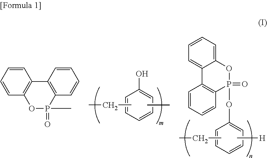
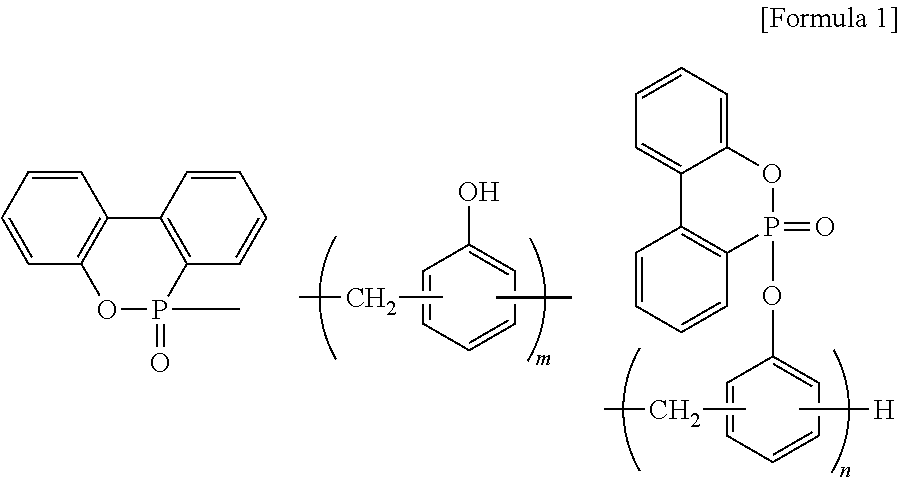
Disclosed is an epoxy resin composition comprising: (A) a polymerized compound including, as structural components, phosphaphenanthrene and at least one constituent selected from a structural unit of a phenolic novolak polymer and a structural unit of a phenolic novolak polymer in which a hydrogen atom of a phenolic hydroxyl group is substituted by phosphaphenanthrene; (B) an epoxy resin having two or more epoxy groups in a molecule; and (C) a curing agent that cures the epoxy resin.

Description

TECHNICAL FIELD[0001]The present invention relates to an epoxy resin composition including substantially no halogens, and more particularly to an epoxy resin composition that can be advantageously used as an insulating material for a printed wiring board or the like. The present invention also relates to a prepreg, a metal-clad laminate, and a printed wiring board using such epoxy resin composition.BACKGROUND ART[0002]Epoxy resin compositions are widely used as printed wiring board materials because of excellent adhesiveness, electric insulating properties, and chemical resistance.[0003]Since epoxy resins have comparatively poor flame resistance, halogen flame retardants such as bromine flame retardants or halogen flame retardants demonstrating excellent effect in imparting flame resistance, such as halogen-containing epoxy resin, for example, tetrabromobisphenol A epoxy resins, are typically compounded with the epoxy resin compositions used for printed wiring boards. However, the p...

Claims


Application Information

Patent Timeline
IPC IPC(8): C08L85/02H05K1/03C08G79/04
CPCC08G59/4021C08G59/621C08J5/24C08J2363/00C08L85/02H05K1/0373H05K2201/012C08G79/04H05K1/0366Y10T428/31529C08J5/244C08J5/249C08G59/50C08L63/00
Inventor YAMAGUCHI, MAOARISAWA, TETSUYAARAKI, SYUNJIKASHIHARA, KEIKOSAGARA, TAKASHILIN, LIN
Owner PANASONIC INTELLECTUAL PROPERTY MANAGEMENT CO LTD
Learn More