
Harmonic cancelling interphase magnetic device

a magnetic device and harmonic cancelling technology, applied in the direction of transformer/inductance noise damping, ac-dc conversion, inductance, etc., can solve the problems of destroying the quality of public power supply voltage, malfunction and/or failure of many different kinds of electrical equipment supplied, and achieves better symmetry, reduces the size, weight and cost of a low harmonic power converter

Active Publication Date: 2013-05-16
SCHAFFNER EMV
View PDF0 Cites 14 Cited by
  • Summary
  • Abstract
  • Description
  • Claims
  • Application Information

AI Technical Summary

Benefits of technology

The invention aims to create a magnetic device with a more efficient shape that is smaller, lighter, and cheaper than previous versions. Additionally, it also provides better symmetry for the device.

Problems solved by technology

If there is not an efficient minimization of the current harmonics, some problems can occur.
First, harmonics can destroy the quality of public power supply voltage and a low quality of the supply voltage causes malfunction and / or failure of many different kinds of electrical equipment supplied by the public power grid.
Moreover harmonics can cause excessive losses in the components of the power grid such as transformers, power lines, etc.
Further, harmonics have audible frequencies: if the power line polluted by harmonics is in the vicinity of an audible equipment installation, an audible distortion can be induced.
They reduce the harmonic currents and are very reliable but have some disadvantages: first they require a bulky and expensive line-frequency input power transformer to create galvanic isolation; moreover they are sensitive to voltage unbalance.
Passive filters have low power losses but are costly and have a big size and a big weight.
Active filters are regarded as less reliable, have higher power losses and switching distortions, and are quite expensive.
Even if its size and weight can be attractive and its cost can be lower than other solutions, it presents some disadvantages, in particular it is perceived as less reliable and it is difficult to match the power losses and the switching distortions of a passive system.
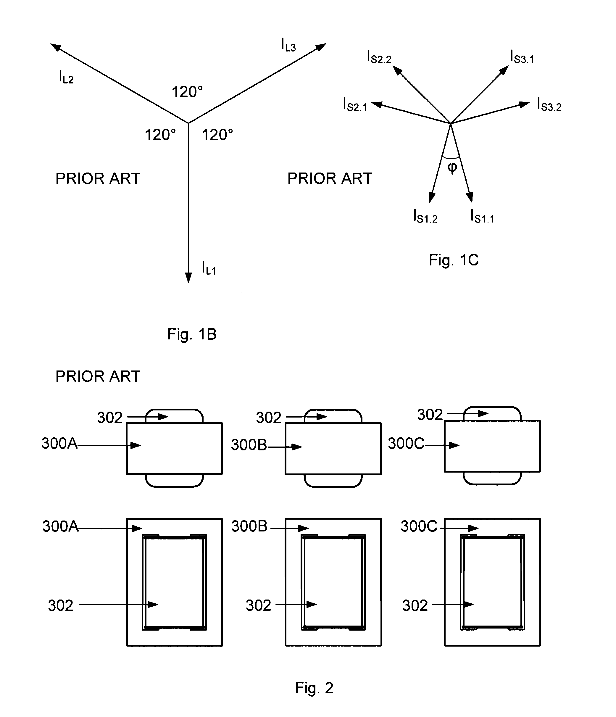
This solution has the drawback of requiring at least four magnetic cores as discussed, so that it is voluminous and expensive.
Moreover the shape of these cores is not designed to allow a possible optimization and then a lower size and a lower cost of the magnetic device.
Moreover the total number of the windings is quite high, i.e. superior to nine, and it is difficult to reduce.
When such a non inductive splitter is used in combination with a low impedance DC link rectifier, which is the most popular case, it requires an additional inductor or choke for having CCM so that the whole system requires more material and is then more voluminous and more expensive.
The solutions described in the prior art for inductive and not inductive splitter in the other terms are not optimised for reducing the cost and the size of a low harmonic power converter.

Method used


Image

  • Harmonic cancelling interphase magnetic device
  • Harmonic cancelling interphase magnetic device
  • Harmonic cancelling interphase magnetic device

Examples


Embodiment Construction

[0077]The magnetic device of the invention is designed for a power converter. Its use enables a reduction of the harmonics of the currents drawn by the converter from three phase power line. It has a lower cost and size compared to the state of art solutions.

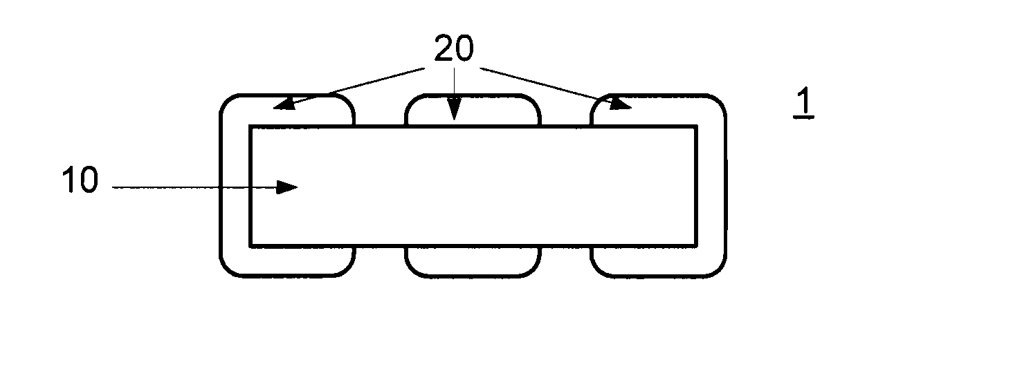
[0078]FIGS. 9A, 9B, 9C and 9D show respectively a top view, a side view, a cross-section of the top view and another side view of one possible embodiment of the device 1 according to the invention. In this embodiment the device 1 has a rectangular shape and comprises a connected and without air-gaps magnetic core 10 with five legs: three wound legs 12 and two non-wound legs 14. Each wound leg 14 contains a bobbin 20 with some windings.

[0079]This device is not simply obtained by combining three separated cores known in the state of the art: the connection of three separated cores implicates the cancelation of the fundamental component of the magnetic flux generated by the currents flowing into the windings. Only the harmonics of ...


PUM


Abstract

A harmonic cancelling interphase magnetic device (1) comprising a magnetic core of rectangular shape with three wound legs (14) and two non-wound legs (12), wherein the cross-section of said non-wound legs (12) is thinner than the cross-section of said wound legs (14). The magnetic device is designed for a front end multi-pulse rectifier or inverter. Its use enables reduction of the harmonics of the currents absorbed or injected to three-phase power line. Compare to known solutions, cost, material and dimensions of the magnetic device are significantly reduced.

Description

REFERENCE DATA[0001]This application is a continuation of International Patent Application PCT / EP2010 / 058157 (W02011154040) filed on Jun. 10, 2010, the contents whereof are hereby incorporated by reference.FIELD OF THE INVENTION[0002]Embodiments of the present invention concern a harmonic cancelling interphase magnetic device for a low harmonic AC / DC and DC / AC converter, and bidirectional front-end including such device.DESCRIPTION OF PRIOR ART[0003]The widespread use of power electronic equipment has increased the need of minimization of power lines harmonic pollution. Main source of current harmonics are non-linear power loads. An important non-linear power load is the six-pulse rectifier, which is widely used as a front-end solution for the majority of the three-phase equipments.[0004]If there is not an efficient minimization of the current harmonics, some problems can occur. First, harmonics can destroy the quality of public power supply voltage and a low quality of the supply v...

Claims


Application Information

Patent Timeline
IPC IPC(8): H01F27/33H02M1/12
CPCH01F2038/026H02M1/126H02M7/06H02M7/2173H02M7/493H02M1/12H01F30/12H01F37/00H01F27/33
Inventor PIETKIEWICZ, ANDRZEJ
Owner SCHAFFNER EMV
Learn More