
Short light pulse generating device, terahertz wave generating device, camera, imaging device, and measuring device

a terahertz wave and generating device technology, applied in the field of short light pulse generating device, terahertz wave generating device, camera, imaging device, measuring device, etc., can solve the problems of increased manhours, poor optical coupling efficiency of semiconductor laser components and pulse compressing parts, and extremely difficult optical alignment, etc., to achieve high light utilization efficiency

Inactive Publication Date: 2013-05-16
SEIKO EPSON CORP
View PDF0 Cites 6 Cited by
  • Summary
  • Abstract
  • Description
  • Claims
  • Application Information

AI Technical Summary

Benefits of technology

The patent text describes a measuring device that uses a distributed feedback semiconductor laser component to generate light pulses. The device integrates the light pulse generating part and the pulse compressing part, improving the coupling efficiency. However, a problem arises during the manufacturing process when selectingively producing a diffraction grating within the semiconductor laser component. Complex processes, decreased yield, and increased manufacturing cost are required. The patent aims to provide a solution for high light utilization efficiency without complicated manufacturing processes.

Problems solved by technology

However, with the semiconductor short pulse laser components noted in Japanese Patent No. 3328881 and Japanese Patent No. 3014039, when using an edge emitting type semiconductor laser component using a cleavage surface as a reflecting mirror as the light pulse generating part, it is necessary to separate the light pulse generating part and the pulse compressing part, so optical coupling is performed using an optical product such as a lens or the like, but the cross section area of the optical waveguide of the pulse compressing part is extremely narrow, and optical alignment is extremely difficult, so the optical coupling efficiency of the semiconductor laser component and the pulse compressing part is poor.
As a result, there is an increase in manhours required for optical alignment, and the need further arises to increase the light output of the light pulse generating part to obtain the required light output, so there is a problem of increased power consumption.
Also, when using a distributed feedback semiconductor laser component as the light pulse generating part, it is not necessary to separate the light pulse generating part and the pulse compressing part, so it is possible to make the light pulse generating part and the pulse compressing part as an integrated unit, which improves the coupling efficiency, but it is necessary to selectively produce a diffraction grating within the semiconductor laser component, resulting in problems of the manufacturing process becoming complex, yield decreasing, and the manufacturing cost rising.

Method used


Image

  • Short light pulse generating device, terahertz wave generating device, camera, imaging device, and measuring device
  • Short light pulse generating device, terahertz wave generating device, camera, imaging device, and measuring device
  • Short light pulse generating device, terahertz wave generating device, camera, imaging device, and measuring device

Examples


first embodiment

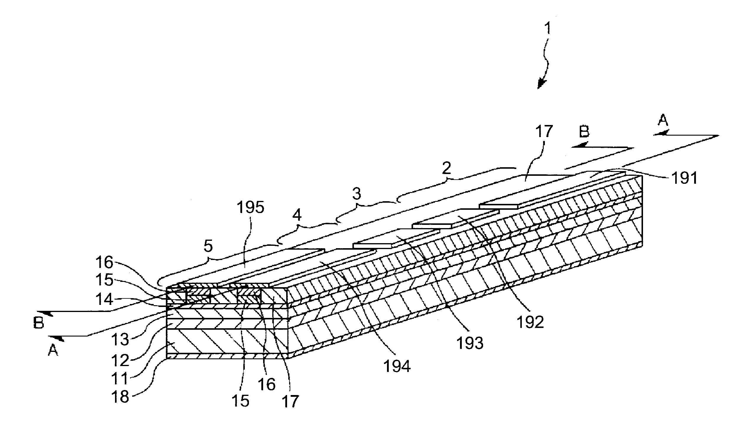
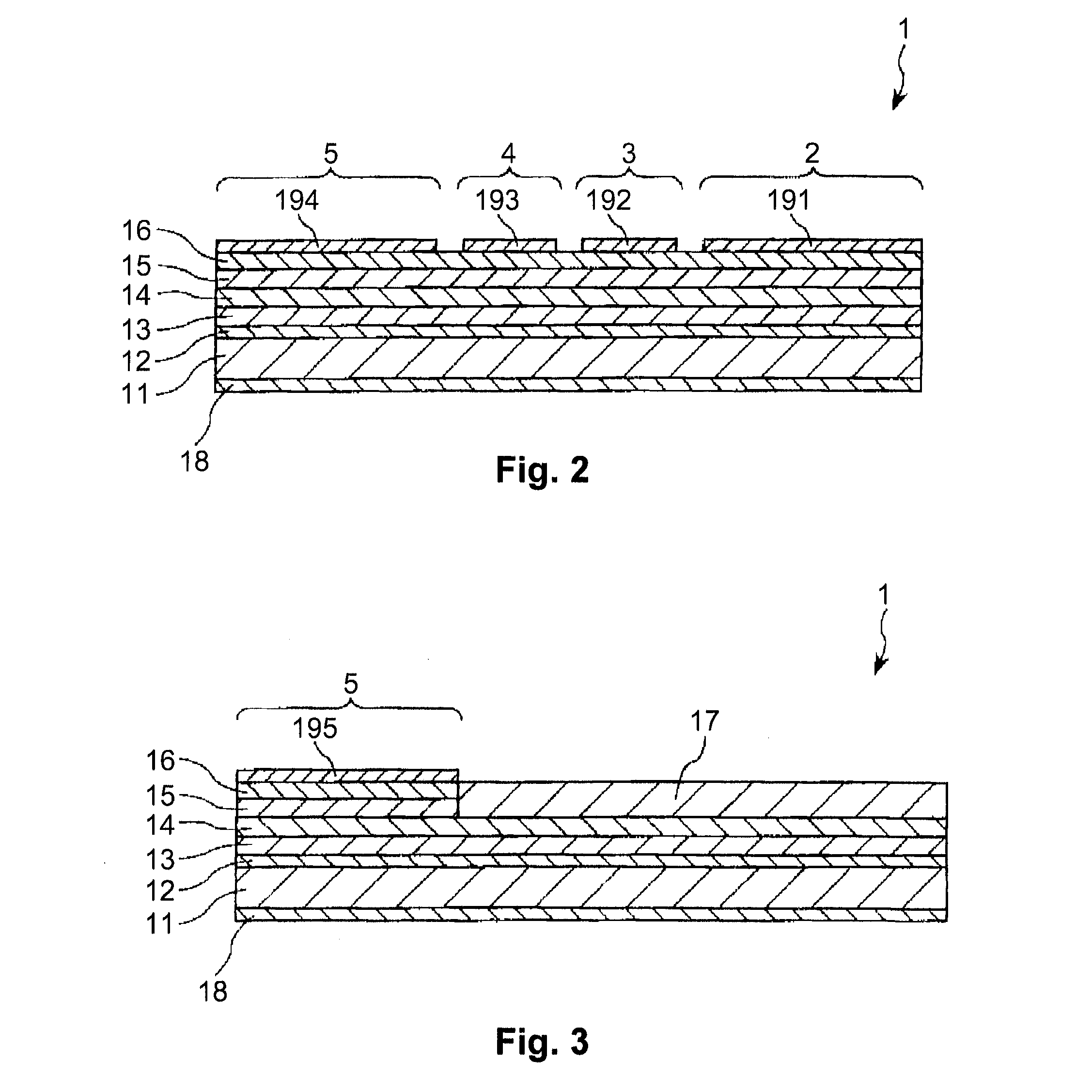
[0046]FIG. 1 is a perspective view of the semiconductor short pulse generating device of the present invention. FIG. 2 is a cross section view of line A-A in FIG. 1. FIG. 3 is a cross section view of line B-B in FIG. 1.

[0047]As shown in FIG. 1 to FIG. 3, the semiconductor short pulse generating device (short light pulse generating device) 1 has a light pulse generating part 2 for generating light pulses, a first pulse compressing part 3 for performing pulse compression on the light pulses generated by the light pulse generating part 2, a second pulse compressing part 5 for performing pulse compression on the light pulses for which pulse compression was done by the first pulse compressing part 3, and an amplifying part 4 for amplifying light pulses.

[0048]The amplifying part 4 is provided at the front part of the first pulse compressing part 3, or between the first pulse compressing part 3 and the second pulse compressing part 5, but with the constitution in the drawings, the amplifyi...

second embodiment

[0064]FIG. 4 is a perspective view showing a semiconductor short pulse generating device of the second embodiment of the semiconductor short pulse generating device of the present invention.

[0065]Following, for the second embodiment, the description focuses on the differences from the previously described first embodiment, and a description will be omitted for items that are the same.

[0066]As shown in FIG. 4, with the semiconductor short pulse generating device 1A of the second embodiment, a plurality of unitary units 6 are equipped, with the light pulse generating part 2, the first pulse compressing part 3, the amplifying part 4, and the second pulse compressing part 5 as unitary units 6, and these unitary units 6 are provided in parallel, specifically, put into array form. Each unitary unit 6 respectively correlates to the semiconductor short pulse generating device 1 of the first embodiment.

[0067]With the configuration in the drawing, there are four unitary units 6, but the numbe...

third embodiment

[0070]FIG. 5 is a plan view of the third embodiment of the semiconductor short pulse generating device of the present invention. With FIG. 5, the waveguide 71 is shown with a dashed line, and the light pulse generating part 2, the first pulse compressing part 3, the amplifying part 4, and the second pulse compressing part 5 are respectively shown enclosed by dot-dashed lines.

[0071]Following, the third embodiment will be described with a focus on the differences from the first embodiment, and a description will be omitted of items that are the same.

[0072]As shown in FIG. 5, with the semiconductor short pulse generating device 1B of the third embodiment, the waveguide 71 is alternately bent a plurality of times. Specifically, the waveguide 71 is formed in a zigzag. To say this another way, it has a first waveguide extending in a first direction, a second waveguide extending in a second direction, and a connecting waveguide connecting the first waveguide and the second waveguide.

[0073]...


PUM

PropertyMeasurementUnit
frequenciesaaaaaaaaaa
frequencyaaaaaaaaaa
frequencyaaaaaaaaaa

Abstract

A short light pulse generating device includes a light pulse generating part, a first pulse compressing part, a second pulse compressing part, and an amplifying part. The light pulse generating part is configured to generate light pulses, the light pulse generating part being a super luminescent diode. The first pulse compressing part is configured to perform pulse compression based on saturable absorption on the light pulses generated by the light pulse generating part. The second pulse compressing part is configured to perform pulse compression based on group velocity dispersion compensation on the light pulses that underwent the pulse compression by the first pulse compressing part. The amplifying part is provided between the first pulse compressing part and the second pulse compressing part, and configured to amplify the light pulses that underwent the pulse compression by the first pulse compressing part.

Description

CROSS-REFERENCE TO RELATED APPLICATIONS[0001]This application claims priority to Japanese Patent Application No. 2011-249420 filed on Nov. 15, 2011. The entire disclosure of Japanese Patent Application No. 2011-249420 is hereby incorporated herein by reference.BACKGROUND[0002]1. Technical Region[0003]The present invention relates to a short light pulse generating device, and a terahertz wave generating device, camera, imaging device, and measuring device equipped with a short light pulse generating device.[0004]2. Related Art[0005]In recent years, attention has been devoted to terahertz waves, which are electromagnetic waves with frequencies of 100 GHz or greater and 30 THz or less. Terahertz waves can be used in various forms of measurement and non-destructive testing such as imaging and spectrometry.[0006]An example of a terahertz wave generating device is a photoconductive antenna terahertz wave generating device. This terahertz wave generating device has a light pulse generating...

Claims


Application Information

Patent Timeline
Patent Type & Authority Applications(United States)
IPC IPC(8): H01S5/00H04N5/33G01N21/17G02F1/017G01N21/35G01N21/3581G02F1/025
CPCH01S5/0057G01N21/17H04N5/33G01N21/3586H04N5/2256H04N5/335H01S2301/17H01S5/026H01S5/0265H01S5/0601H01S5/1003H01S5/1085H01S5/4031H01S5/0092H04N23/56H04N25/00H04N23/20
Inventor NAKAYAMA, HITOSHI
Owner SEIKO EPSON CORP
Learn More