
Optimal power supply topologies for switched current-driven leds

a power supply topology and led technology, applied in the direction of lighting apparatus, electroluminescent light sources, light sources, etc., can solve the problems of switching and conduction loss, cost, weight, efficiency, cost and volume, etc., and achieve the effect of reducing optical performance, cost, volume and weight advantages

Active Publication Date: 2013-05-16
HONEYWELL INT INC
View PDF2 Cites 25 Cited by
  • Summary
  • Abstract
  • Description
  • Claims
  • Application Information

AI Technical Summary

Benefits of technology

The present invention proposes a new way to power LEDs using a high-frequency pulse-width modulated switched current instead of output bulk capacitors and freewheeling diodes. This approach provides efficiency, cost, volume, and weight advantages over existing solutions. The LEDs' average current control is done using a feedback loop that senses the average value of LEDs' current and controls the current by varying the pulse width of applied current. This new method does not degrade optical performance and allows for the control of LEDs' current using a more efficient and cost-effective mechanism.

Problems solved by technology

All these solutions suffer in terms of efficiency, cost, weight and volume because of the output filter capacitor and freewheeling diodes.
Although this solution suffers in terms of efficiency, weight, cost and volume due to use of freewheeling diodes.
Freewheeling diodes create switching and conduction losses which reduces efficiency and require bulkier heat-sinks for larger heat dissipation.
In order to improve the efficiency and reduce heat-sink requirements, fast recovery and / or Schottky silicon carbide diodes are used; however this increases the cost of LED drivers.

Method used


Image

  • Optimal power supply topologies for switched current-driven leds
  • Optimal power supply topologies for switched current-driven leds
  • Optimal power supply topologies for switched current-driven leds

Examples


Embodiment Construction

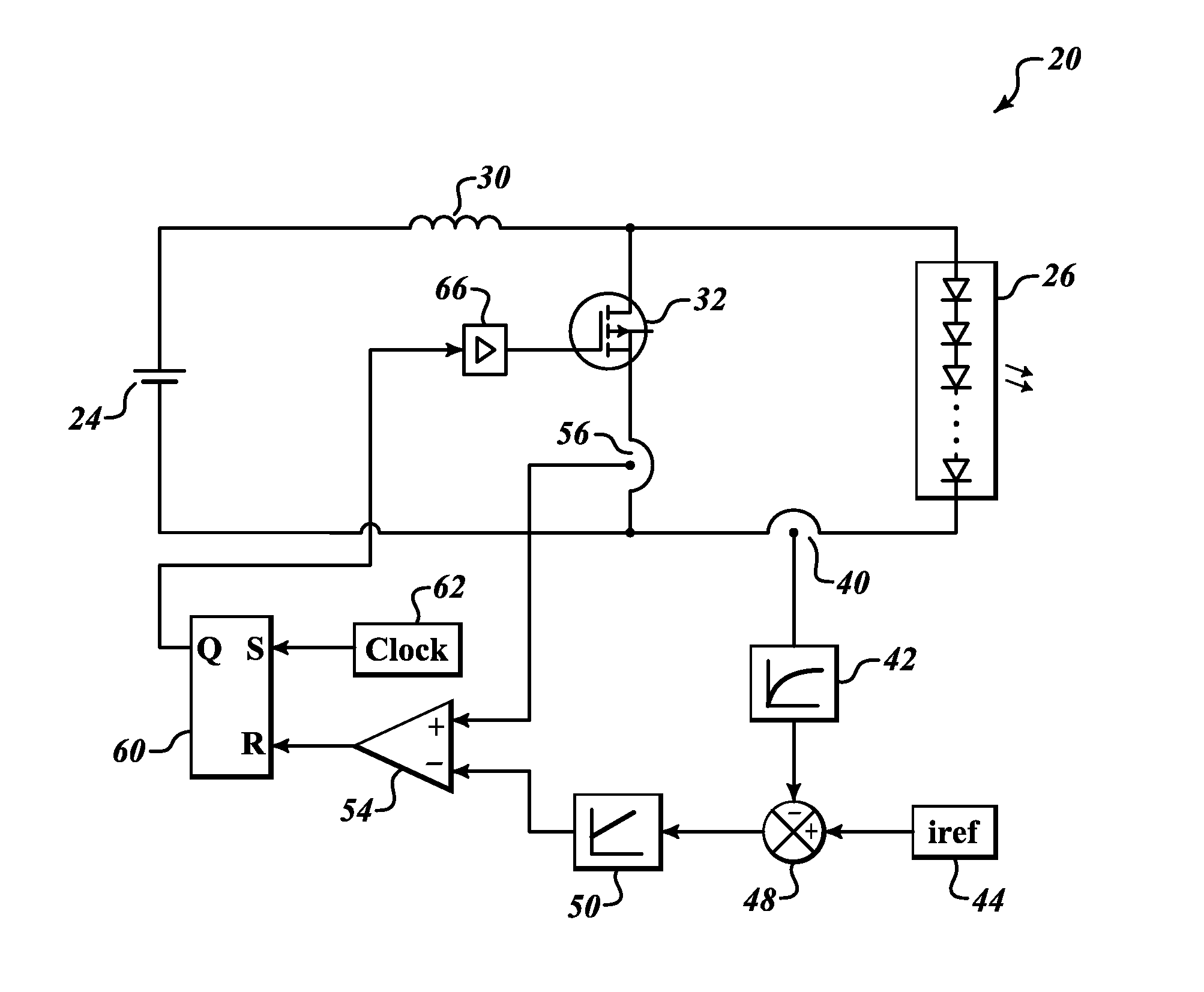
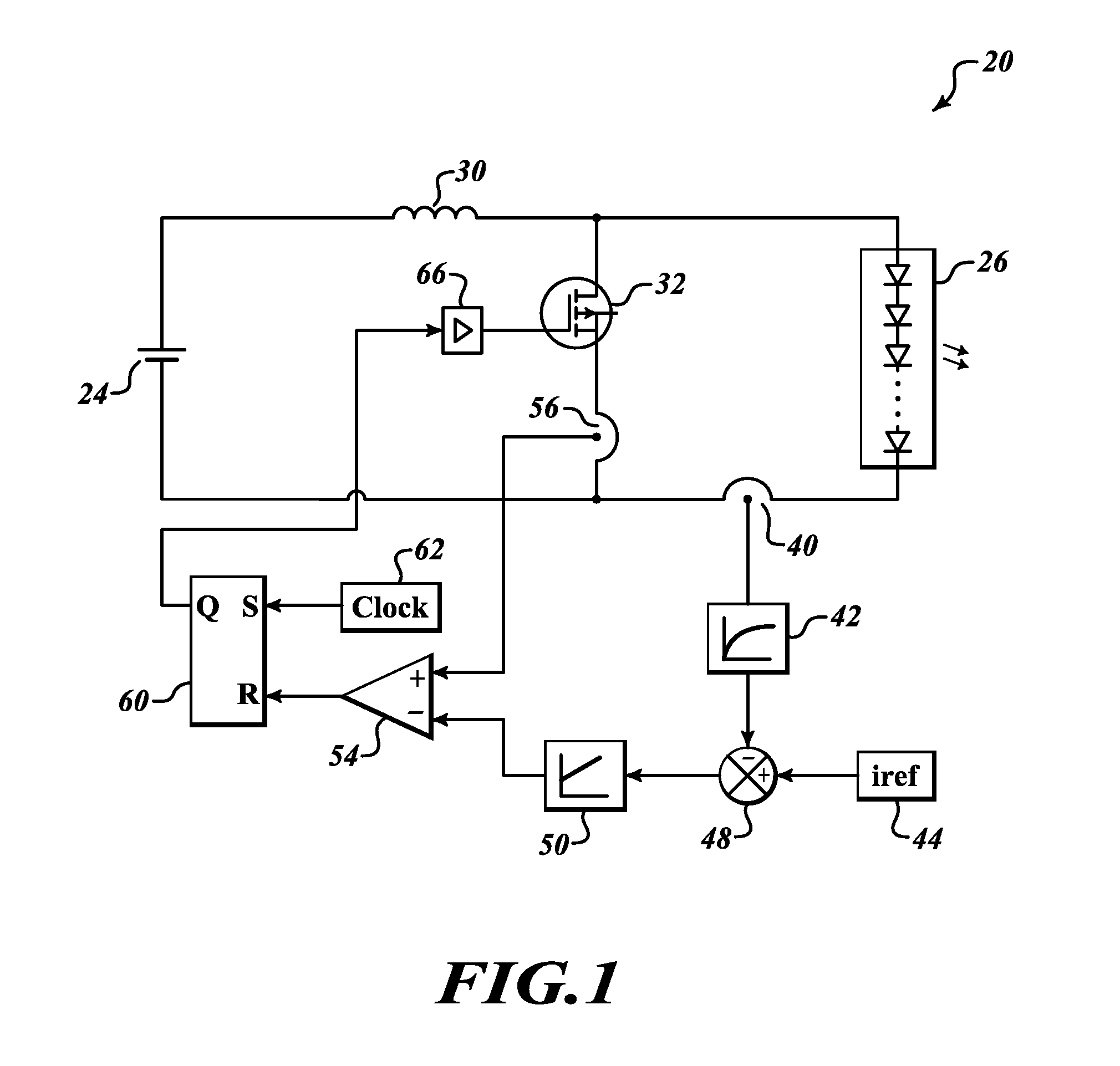
[0011]FIG. 1 shows exemplary power and control circuit 20 according to an embodiment of present invention. The power and control circuit 20 includes a direct current (DC) voltage source 24, which supplies required power to drive sufficient current to an LED string 26 through a switching network formed by an input inductor 30 and an actively controlled power semiconductor switch 32. The LED string 26 includes any number of LEDs in series depending upon the application requirement. This topology is recommended for applications in which voltage requirements of the LED string are higher than the input voltage source 24. A first end of the inductor 30 is connected to the positive lead of the DC voltage source 24. A second end of the inductor 30 is connected to a drain (or source depending upon the type of switch) of the semiconductor switch 32 and an anode end of the LED string 26. The cathode end of the LED string 26 is connected to the source (or drain depending upon the type of switch...


PUM


Abstract

Optimal power supply topologies that do not use output bulk capacitors as well as freewheeling diodes in output section to therefore provide efficiency, cost, volume, and weight advantage over the existing solutions. The present invention applies a pulse-width modulated switched current at higher frequency (in order of 10 to 100 kHz) to LEDs without degrading optical performance. LEDs' average current control is attained using a feedback loop that senses the average value of LEDs' current and controls the current by varying the pulse width of applied current.

Description

BACKGROUND OF THE INVENTION[0001]Recently light emitting diode (LED) based lighting solutions are gaining popularity over traditional light sources such as incandescent lamps, Fluorescent Lamp, Halogen lamps, and high intensity discharge (HID) lights. LED offers highly reliable and energy efficient lighting solutions. LED light output is controlled by forward current flowing through it, hence LED-based lighting solutions need current control electronic circuits. Cost, volume, weight and efficiency of electronics driver circuit's components play a major role in order to make LED lighting solutions successful for retrofit applications as well as new products developments.[0002]The constant current sources for LEDs are derived using standard DC-DC converter topologies. These may include non-isolated DC-DC converters such as buck, boost, buck-boost, Sepic / cuk converters, or isolated topologies like fly back, forward converters etc. The control logic for these power supplies is modified ...

Claims


Application Information

Patent Timeline
IPC IPC(8): H05B37/02
CPCH05B33/0815Y02B20/347H05B33/0848H05B45/14H05B45/3725H05B45/375H05B45/38Y02B20/30
Inventor SAXENA, SUNIT K.RAJNE, MILANDE, SUKUMAR
Owner HONEYWELL INT INC
Learn More