Heat sink device

a heat sink and heat pipe technology, applied in the direction of solid-state devices, semiconductor/solid-state device details, electrical apparatus construction details, etc., can solve the problems of high heat dissipation requirements, inconvenience for electrical connections, large volume of aluminum extrusion heat sinks, etc., to reduce the layout space of power elements, reduce the working temperature of power elements, and improve the thermal conductivity of heat pipes

Active Publication Date: 2013-05-02
DELTA ELECTRONICS SHANGHAI CO LTD
View PDF11 Cites 7 Cited by
  • Summary
  • Abstract
  • Description
  • Claims
  • Application Information

AI Technical Summary

Benefits of technology

[0017]In the application of the heat sink device of this disclosure, the evaporation section of the heat pipe is buried in the inner layer of the heat dissipation substrate, and a portion of the power elements and the other portion of the power elements of the high-power medium-voltage drive power cell are respectively disposed on two side surfaces of the heat dissipation substrate, thereby significantly reducing working temperatures of the power elements due to an excellent thermal conductivity of the heat pipe. Moreover, the power elements of the drive are disposed on two side surfaces of the heat dissipation substrate respectively, thereby effectively reducing the layout space of the power elements and further reducing the volume of the heat dissipation substrate.

Problems solved by technology

This structure causes high heat dissipation requirements.
When a large heat sink, the distance between the power modules is relatively large and the layout is non-compact, which further causes inconvenience for the electrical connections and matching between the power elements and electrolytic capacitor assemblies.
Moreover, the aluminum extrusion heat sink has a large volume, a heavy weight and a high cost, so that the aluminum extrusion heat sink is disadvantageous to the saving of system installation cost.

Method used


Image

  • Heat sink device
  • Heat sink device
  • Heat sink device

Examples


Embodiment Construction

[0021]Specific embodiments of the present invention are further described in detail below with reference to the accompanying drawings.

[0022]In order to make the description of the present invention more detailed and more comprehensive, various embodiments are described below with reference to the accompanying drawings. The same reference numbers are used in the drawings to refer to the same or like elements. However, the embodiments described are not intended to limit the present invention. Moreover, it is not intended for the description of operation to limit the order of implementation. Any device with equivalent functions that is produced from a structure formed by a recombination of elements shall fall within the scope of the present invention.

[0023]The drawings are only illustrative and are not drawn to actual size. Additionally, well-known elements and steps are not described in the embodiments to avoid causing unnecessary limitations to the present invention.

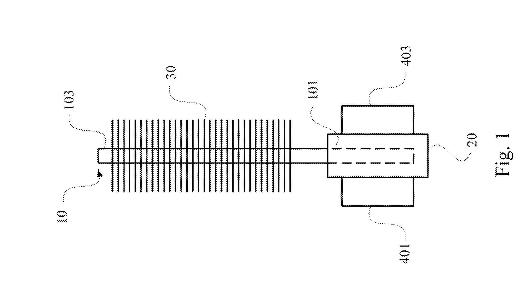
[0024]FIG. 1 is a...


PUM


Abstract

The present invention provides a heat sink device, suitable to the heat dissipation of a high-power medium-voltage drive power cell. The device comprises a heat dissipation substrate having a first surface, a second surface and an inner layer between the first surface and the second surface; a heat pipe having an evaporation section and a condensation section. The evaporation section is buried in the inner layer of the heat dissipation substrate, and the condensation section is used to dissipate the heat from the evaporation section to the air. The power elements of the high-power medium-voltage drive power cell are disposed on the first surface and the second surface, respectively.

Description

RELATED APPLICATIONS[0001]This application claims priority to Chinese Application Serial Number 201110330134.6, filed Oct. 26, 2011, which is herein incorporated by reference.BACKGROUND[0002]1. Field of Invention[0003]The present invention relates to a high-power medium-voltage drive in electrical and electronic fields. More particularly, the present invention relates to a heat sink device suitable for use in a high-power medium-voltage drive power cell.[0004]2. Description of Related Art[0005]With the rapid development of modern electrical and electronic technology and microelectronic technologies, a high-voltage medium-power drive apparatus has increasingly wide applications, such as wind turbines, water pumps, compressors, rolling mills or the like in petrochemical, municipal water supply, die casting, power energy source industries.[0006]There are vast categories for the high-power medium-voltage drive and there also are a variety of sorting methods related thereto. For example,...

Claims


Application Information

Patent Timeline
Patent Type & Authority Applications(United States)
IPC IPC(8): H05K7/20
CPCH02M7/003H01L23/427H02M5/458H01L2924/0002H01L2924/00
Inventor TONG, AI-XINGCHANG, YU-MINGGAN, HONG-JIANMA, SHAO-CAIYING, JIAN-PING
Owner DELTA ELECTRONICS SHANGHAI CO LTD
Why Eureka
Try Eureka