Method for the collision-free positioning of a micromanipulator tool

a technology of micromanipulator and tool, which is applied in the direction of material analysis, position/direction control, instruments, etc., can solve the problems of difficult isolation of individual as well as unusual cells from minute samples necessary for genotype and phenotype characterization, and achieves high accuracy in the calibration of the position. , the effect of speeding up the method

Active Publication Date: 2013-04-11
MONOLITHIC MEMORIES
View PDF8 Cites 2 Cited by
  • Summary
  • Abstract
  • Description
  • Claims
  • Application Information

AI Technical Summary

Benefits of technology

The patent describes a method for improving the accuracy and reliability of a micromanipulation device used in cell microscopy. It uses an objective lens with a small numerical aperture to detect the position of a manipulation tool over a sample carrier, preventing collisions and ensuring precise positioning. The method can be used fully automatically or manually. It reduces the time required for calibration and allows for positioning within a few micrometers of the sample carrier. In addition, the method can be used on a receiving vessel in which cell material is deposited, ensuring consistent deposition position. Overall, this method enhances the function, efficiency, reliability, and user-friendliness of the micromanipulation device.

Problems solved by technology

Hitherto this objective could be achieved only with difficulty and took a not inconsiderable amount of time on account of mechanical and also process technology restrictions in the cell manipulation (e.g. the collection of cells or the microinjection).
In particular the isolation of individual as well as unusual cells from minute samples necessary for the genotype and phenotype characterization proved to be very difficult, since individual cells had to be detected under a microscope by research staff and the detected cells then had to be manipulated manually with the aid of capillaries.
Hitherto it was not possible however to determine in an automated manner with a sufficiently small tolerance the actual position of the manipulator tip in the Z-direction without additional measurement means.
Although some approaches to the automation of this procedure are known, which however in these previously known methods did not take account of the imaging tolerances of the objective lens, damage to the manipulated tip still occurred.
With manual calibration methods on the other hand the handling tools are often not sufficiently accurate, with the result that only very skilled users can master these systems.
A disadvantage with the methods described here is that the distance to the slide (in other words the position at which the capillary can be damaged) is not determined, but simply the Z-coordinate of the surface of an arbitrarily selected cell from the biological sample.
It therefore cannot be excluded that the capillary tip and the slide collide and the capillary is thereby damaged.
Since in this case cells that are indeed derived from the same cell culture but have different external geometries deposit on the slide, this type of calibration to determine the position is very inaccurate.
The disadvantage with this sample manipulation device is that the position measurement objective lens has a depth of focus of the order of magnitude of the manipulator tip, and therefore the determination of the Z-direction is correspondingly inaccurate, with an error that corresponds roughly to the diameter of the capillary itself.
This error is however not taken into account for the positioning.
Also, the position of the slide in the Z-direction is not determined, so that given the possible deviation of the real position from the calculated position on account of the error of the position measurement objective, collisions between the slide and manipulator tip can occur.
When the sampling tool is lowered the tolerances, which are determined for example by the depth of focus of the microscope objective, are furthermore not taken into account, which can lead to an incorrect calculation of the distance to be maintained and thus to collisions.
Although according to DE 10 2007 046 267 A1 an additional sensor or a spring mounting for the manipulation tool can be provided for the case of such a collision, this however does not reliably exclude damage and furthermore leads to defective sampling and therefore to lost time.
Also in the case of obliquely, i.e. not exactly horizontally inserted slides, which is a situation frequently encountered in practice but seldom realised by technical staff, errors in the position of the capillary occur.
The capillary could be damaged already when moving to the start position, especially if the start position is only a few μm from the slide surface.
When using glass Petri dishes the error can finally amount to a multiple of this value.
If however a contact calibration with step widths of 100 μm) would have to be maintained, which in practice leads to significant disadvantages since at step widths<1 μm a contact calibration would then take too much time.

Method used


Image

  • Method for the collision-free positioning of a micromanipulator tool
  • Method for the collision-free positioning of a micromanipulator tool
  • Method for the collision-free positioning of a micromanipulator tool

Examples


Embodiment Construction

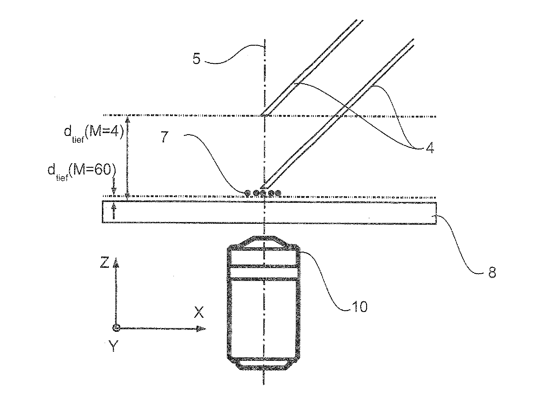
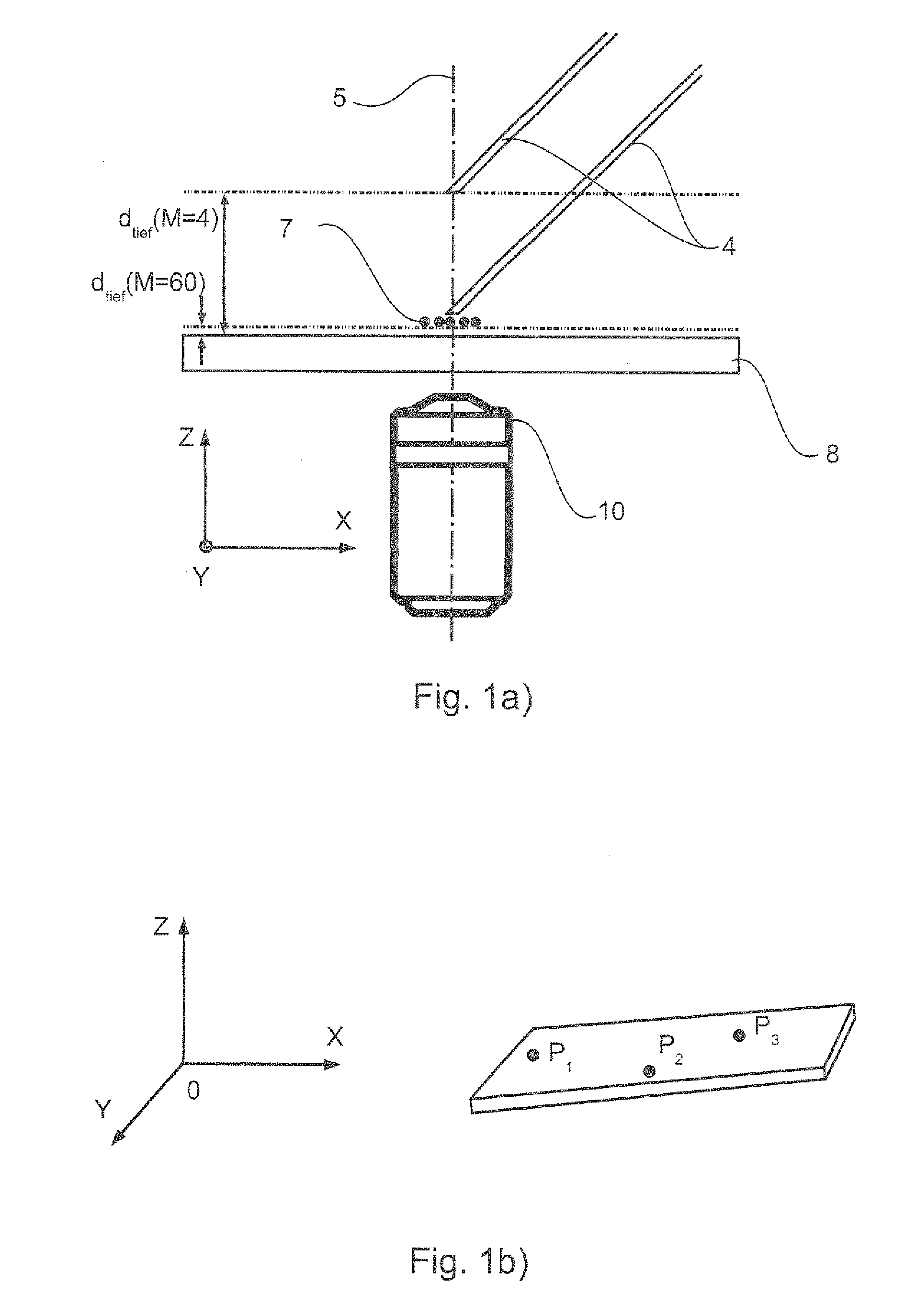
[0010]The object of the present invention is accordingly to provide a method for the collision-free positioning of a micromanipulation tool relative to a sample carrier, which permits an accurate and damage-free positioning of the manipulation tool over the whole sample surface in a completely automated manner. This object is achieved by a method having the features of claim 1. Preferred advantageous configurations of the invention are defined in the dependent claims.

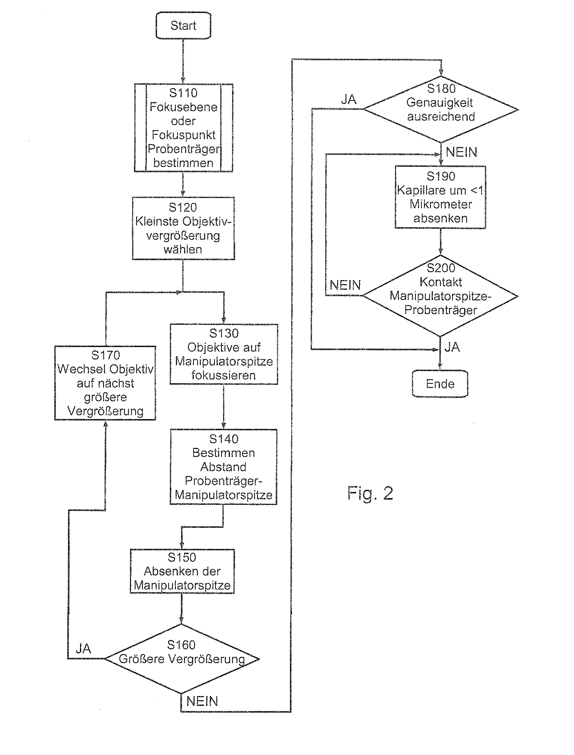
[0011]The method according to the invention for the collision-free positioning of a micromanipulation tool relative to a sample carrier with the aid of a microscope comprises the following steps:

a) determining the focal position 4 of at least one point P on the surface of the sample carrier by focusing a first microscope objective with a first numerical aperture NA1 on the at least one point; b) positioning the micromanipulation tool on the optical axis of the microscope; c) determining the focal position ZM of the micr...


PUM


Abstract

A method for the collision-free positioning of a micromanipulation tool relative to a sample carrier with the aid of a microscope, comprising the following steps: a) determining the focal position Zp of at least one point P on the surface of the sample carrier by focusing a microscope objective with a first numerical aperture NA1 on the at least one point; b) positioning the micromanipulation tool on the optical axis of the microscope; c) determining the focal position ZM of the micromanipulation tool by focusing the microscope objective or a second microscope objective with a second numerical aperture NA2 smaller than the first numerical aperture NA1 onto the tip of the micromanipulation tool; d) calculating the lowering distance ZA(P) taking into account a predetermined tolerance profile ΔZ by the following equation:ZA(P)=ZM−Zp−ΔZ where ΔZ=ΔZM+ΔZp, wherein ΔZM and / or ΔZp is a predetermined tolerance in the determination of the position of the manipulation tool and sample carrier, respectively; and e) positioning the micromanipulation tool at the point P by lowering by the lowering distance ZA(P).

Description

[0001]The present invention relates to a method for the collision-free positioning of a micromanipulation tool, in particular a tool for microinjection, individual cell removal, microdissection and the like.PRIOR ART[0002]The molecular analysis of pure enriched cell cultures or even individual cells is an important prerequisite of medical genomics and proteomics, and could become extremely important in the future for a medical profiling of patients. Hitherto this objective could be achieved only with difficulty and took a not inconsiderable amount of time on account of mechanical and also process technology restrictions in the cell manipulation (e.g. the collection of cells or the microinjection). In particular the isolation of individual as well as unusual cells from minute samples necessary for the genotype and phenotype characterization proved to be very difficult, since individual cells had to be detected under a microscope by research staff and the detected cells then had to be...

Claims


Application Information

Patent Timeline
IPC IPC(8): G05D3/00
CPCG01N1/286G05D3/00G02B21/32
Inventor BRILL, NORBERT
Owner MONOLITHIC MEMORIES
Why Eureka
Try Eureka