
Perpendicular spin torque oscillator FMR frequency measurement method

a technology of perpendicular spin and oscillator, which is applied in the direction of frequency measurement arrangement, record information storage, instruments, etc., can solve the problems of overall stack thickness, difficult to detect the actual fmr frequency of mol b>3/b>, and associated with the prior ar

Active Publication Date: 2013-03-21
TOSHIBA ELECTRONICS DEVICES & STORAGE CORPORARTION +1
View PDF4 Cites 20 Cited by
  • Summary
  • Abstract
  • Description
  • Claims
  • Application Information

AI Technical Summary

Benefits of technology

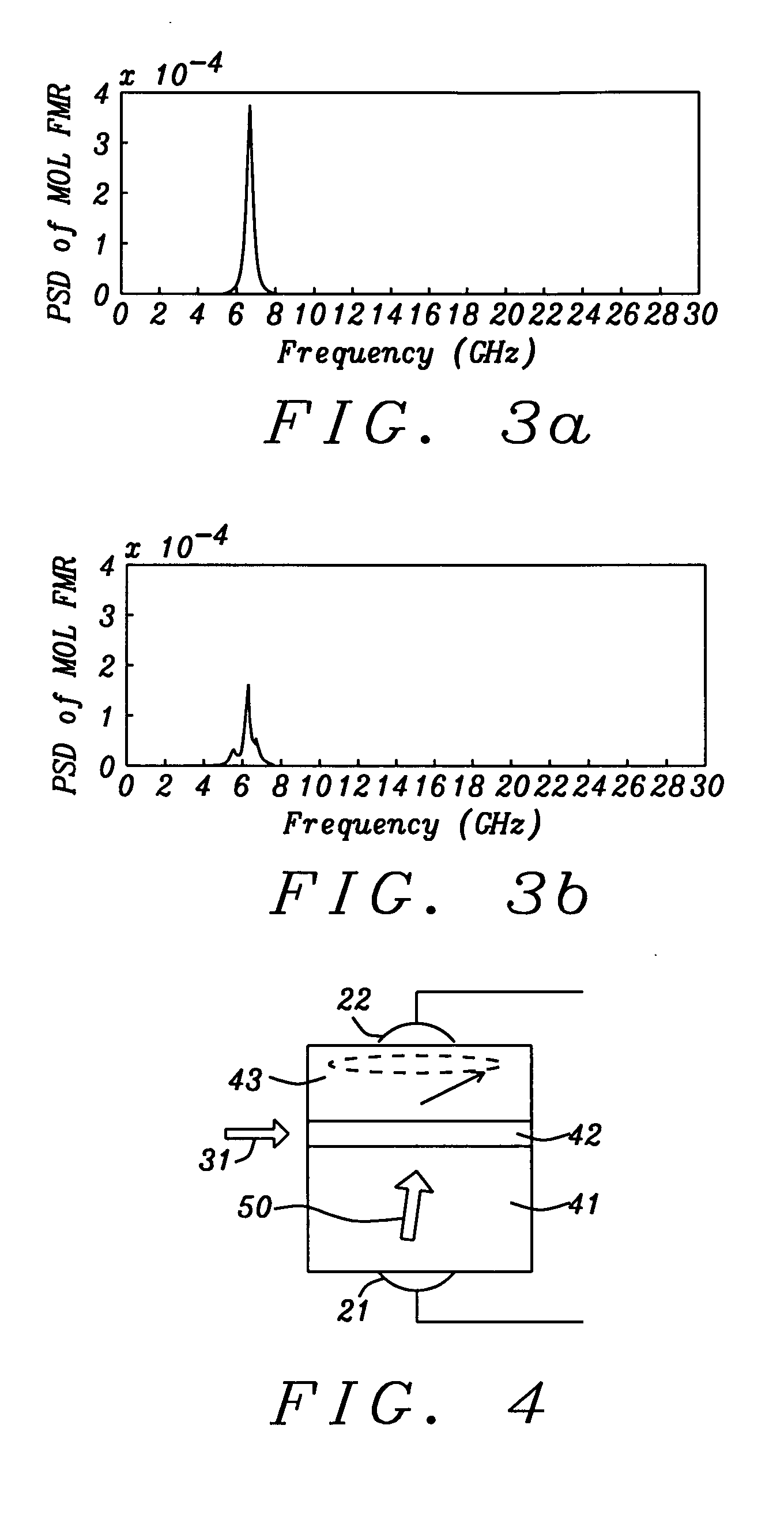
The present invention provides a method for characterizing the oscillation frequency of a PSTO MOL without using a secondary MR junction that interferes with MOL oscillation and without needing an additional device that would limit the density of the PSTO on the substrate. The method involves exciting the MOL into an oscillation state with a current directed perpendicular to the layers of the PSTO and applying a small in-plane magnetic field to the PSTO device. The resulting resistance change is measured as a function of the applied field. The method can be implemented using a MRL with perpendicular magnetic anisotropy. The invention also provides a method for characterizing MOL oscillation frequency by applying a strong field in two directions and using soft magnetic poles to generate a magnetic field that tilts the perpendicular magnetization of the MRL.

Problems solved by technology

As a result, spin valve structures based on PMA are capable of scaling for higher packing density which is a key challenge for future MRAM (Magnetoresistive Random Access Memory) applications and other spintronic devices such as microwave generators.
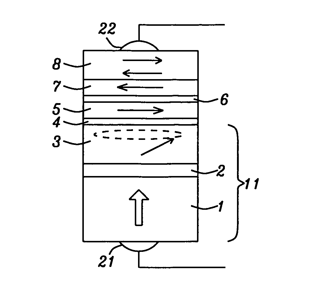
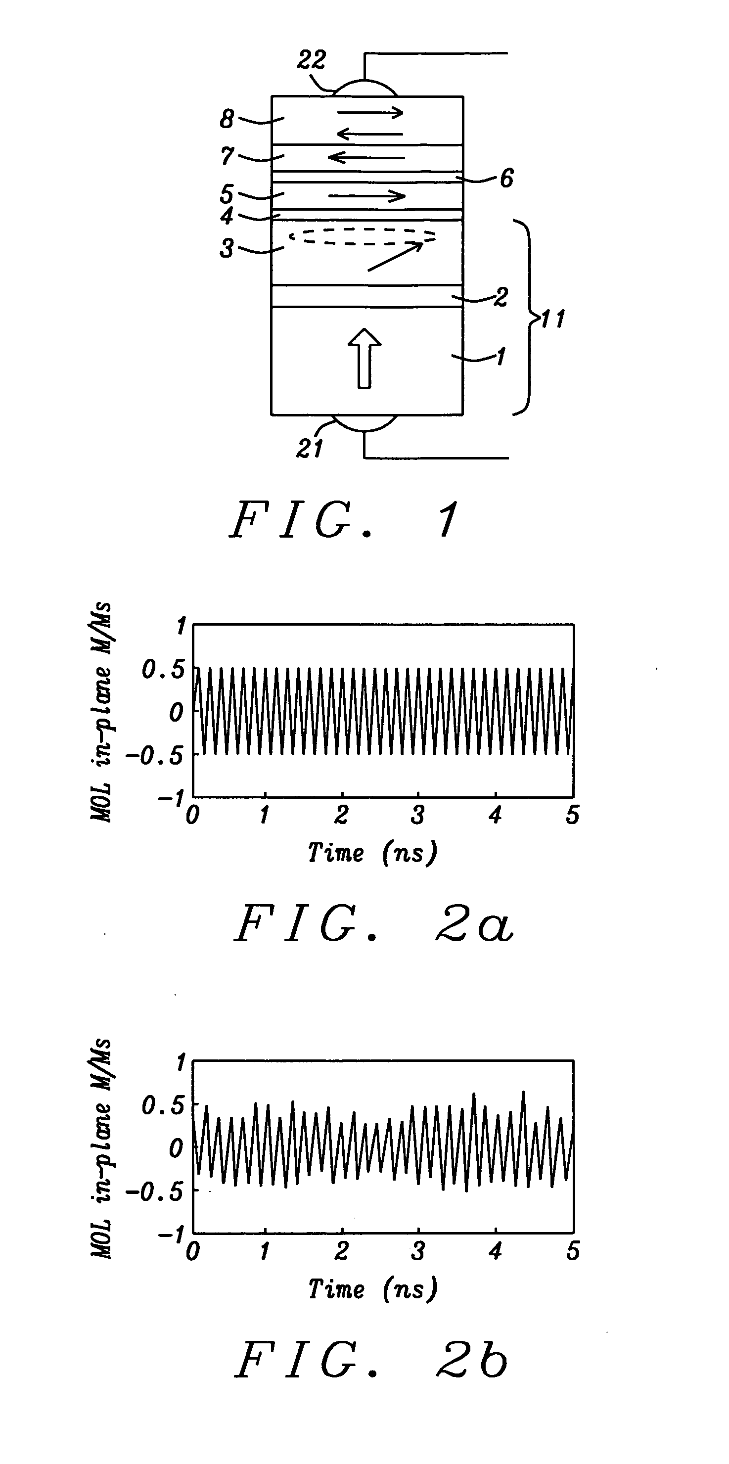
However, when MOL 3 reaches a stable magnetic oscillation with a significant amount of in-plane magnetization component, the relative angle between the magnetizations of MRL 1 and MOL 3 does not really change which makes the detection of the actual FMR frequency of MOL 3 hard to achieve when only measuring the resistance between the MRL and MOL.
However, there are disadvantages associated with the prior art as pictured in FIG. 1.
First of all, the additional layers 4-8 above MOL 3 significantly increase the overall stack thickness and thereby limit its feasibility in thin film applications as in a magnetic recording device.
The change to irregular oscillations and lower power is especially not desirable when uniform and high power MOL oscillation is required on a continuous basis for optimum performance while characterization of oscillation frequency is only needed occasionally, for example, when the PSTO is used as a RF field generator in a magnetic recording device.
However, this approach requires development of two anisotropy axes in the magnetic MRL film, and a MRL film structure that is more complicated than needed in situations where a simple PSTO structure with perpendicular MRL is desired as in examples where a PSTO serves as a RF magnetic field generator in a magnetic recording device.

Method used


Image

  • Perpendicular spin torque oscillator FMR frequency measurement method
  • Perpendicular spin torque oscillator FMR frequency measurement method
  • Perpendicular spin torque oscillator FMR frequency measurement method

Examples


Embodiment Construction

[0027]The present invention is a method relating to the measurement of oscillation frequency in a PSTO device. The perpendicular spin torque oscillator may be employed as a RF field generator in a magnetic recording head for microwave assisted magnetic recording (MAMR) or may be used in other applications such as a reference oscillator or directional microwave transmitter in devices including cell phones, radar systems, and computer chips. Furthermore, in a magnetic recording head device, the PSTO may have a so-called “top” or “bottom” configuration determined by whether the MOL in the MRL / spacer / MOL stack is formed closer to the main pole than the MRL, or if the opposite is true. The magnetic oscillation layer (MOL) as described herein may be considered a “free” ferromagnetic layer in that its magnetization orientation is free to change (oscillate) in the presence of a direct current flowing perpendicular to the plane of the MOL. The junction layer in the PSTO stack may also be ref...


PUM


Abstract

A method for measuring the frequency in a spin torque oscillator having at least a magnetic oscillation layer (MOL), junction layer, and magnetic reference layer (MRL) is disclosed. In a first embodiment, a small in-plane magnetic field is applied to the STO after a DC current is applied to excite the MOL into an oscillation state. The MRL has a perpendicular magnetization that is tilted slightly to give an in-plane magnetization component to serve as a reference layer for measuring the oscillation frequency of the MOL in-plane magnetization component. An AC voltage change is produced in the DC current as a result of variable STO resistance and directly correlates to MOL oscillation frequency. Alternatively, a field having both perpendicular and in-plane components may be applied externally or by forming the STO between two magnetic poles thereby producing an in-plane magnetization reference component in the MRL.

Description

FIELD OF THE INVENTION[0001]The invention relates to a perpendicular spin torque oscillator (PSTO) used for thin film applications such as a RF field generator in a magnetic recording device, and in particular to a method for determining the PSTO oscillation frequency without causing any permanent change in the PSTO structure or to the magnetic oscillator layer (MOL) behavior therein.BACKGROUND OF THE INVENTION[0002]Spin transfer (Spin torque) devices are based on a spin-transfer effect that arises from the spin dependent electron transport properties of ferromagnetic-spacer-ferromagnetic multilayers. When a spin-polarized current transverses a magnetic multilayer in a CPP (current perpendicular to plane) configuration, the spin angular moment of electrons incident on a ferromagnetic layer interacts with magnetic moments of the ferromagnetic layer near the interface between the ferromagnetic and non-magnetic spacer. Through this interaction, the electrons transfer a portion of their...

Claims


Application Information

Patent Timeline
IPC IPC(8): G01R23/02
CPCG01R33/1284G11C11/1675G11C11/161G11C11/1673G11B5/3903H10N50/10
Inventor ZHOU, YUCHENZHANG, KUNLIANGLI, MINTAKANO, KENICHISMYTH, JOEDOVEK, MORISTAKEO, AKIHIKOFUNAYAMA, TOMOMITAKASHITA, MASAHIROTAKAGISHI, MASAYUKI
Owner TOSHIBA ELECTRONICS DEVICES & STORAGE CORPORARTION
Learn More