
Light-emitting element having nitride semiconductor multiquantum barrier, and process for production thereof

a light-emitting element and semiconductor technology, applied in semiconductor/solid-state device manufacturing, semiconductor devices, electrical equipment, etc., can solve the problems of limited general purpose applications of conventional uv light sources, low -type concentration in algan, and difficult general purpose applications, etc., to improve the electron blocking effect, the barrier height is higher, and the mqb period is longer

Active Publication Date: 2013-03-21
RIKEN
View PDF2 Cites 56 Cited by
  • Summary
  • Abstract
  • Description
  • Claims
  • Application Information

AI Technical Summary

Benefits of technology

The patent text explains that using MQB (Multiple-Barrier) technology results in better electron blocking effects than using a single barrier. The higher the barrier height and the longer the MQB period, the better the electron blocking effects. Additionally, the patent explains that MQB can achieve electron blocking for a wide range of energy levels by changing the MQB periods alternately. This means that MQB can achieve greater electron blocking effects than using the same number of periods.

Problems solved by technology

Conventional UV light sources are limited to gas-solid UV light sources such as excimer lasers, argon ion SHG lasers, and excimer lamps.
Since they are large-size, short-life, and expensive UV light sources, applications thereof for general purposes have been difficult.
Nevertheless, the p-type concentration in AlGaN is still low, causing the efficiency for electron injection into a light-emitting layer to remain at a low level of about 10% to 30%.
In particular, it has been long believed that achievement of high electron injection efficiency would be impossible because p-type AlGaN has limited physical properties, making it impossible to improve the hole concentration of p-type AlGaN.

Method used


Image

  • Light-emitting element having nitride semiconductor multiquantum barrier, and process for production thereof
  • Light-emitting element having nitride semiconductor multiquantum barrier, and process for production thereof
  • Light-emitting element having nitride semiconductor multiquantum barrier, and process for production thereof

Examples


embodiment 1

[0109]FIG. 11 ((a) and (b)) shows energy dependences of electron transmission coefficients obtained using a single barrier and an MQB based on the results of FIGS. 10A and 10B. A combination of barrier periods is used so as to achieve high electron reflection at the highest possible energy levels greater than the energy level of the barrier band edge. FIG. 11 shows the following: (a) an example of an MQB structure in which the barrier period increases in order from the MQW side; and (b) an example of an MQB structure in which the barrier period increases in order from the opposite side. Energy dependences of electron transmission coefficients in both cases are lower than those shown in examples of FIGS. 10A and 10B in a wide range. It is understood that electron-blocking layers shown in FIG. 11 are very useful. The effective barrier height is about 3.5 times greater than that for a single barrier.

[0110]A comparison of (a) and (b) in FIG. 11 shows that there is no dependence associat...

embodiment 2

[0120]The characteristics of a C-plane-grown polar crystal are described below. Each of FIGS. 17A to 20 shows characteristics of C-plane-grown (but not A-plane-grown) MQBs substantially similar to those obtained in Embodiment 1. For a polar MQB, MQB effects basically tend to be similar to those for a non-polar MQB.

[0121]However, the band gradient causes blurred reflectance, making the effects of a polar MQB relatively complicated. The characteristics obtained in the case of a polar MQB are described in detail below.

[0122]For a polar MQB, even the barrier energy of a single barrier shows a cutting blade form, and thus the electron barrier is originally higher than that for a non-polar MQB. Accordingly, an increase in the effective barrier height derived from such MQB becomes smaller than that for a non-polar MQB.

[0123]In order to form sharp cutting blade shapes of MQB barriers and increase the barrier heights to the maximum possible levels, it is desirable to increase the barrier / val...


PUM


Abstract

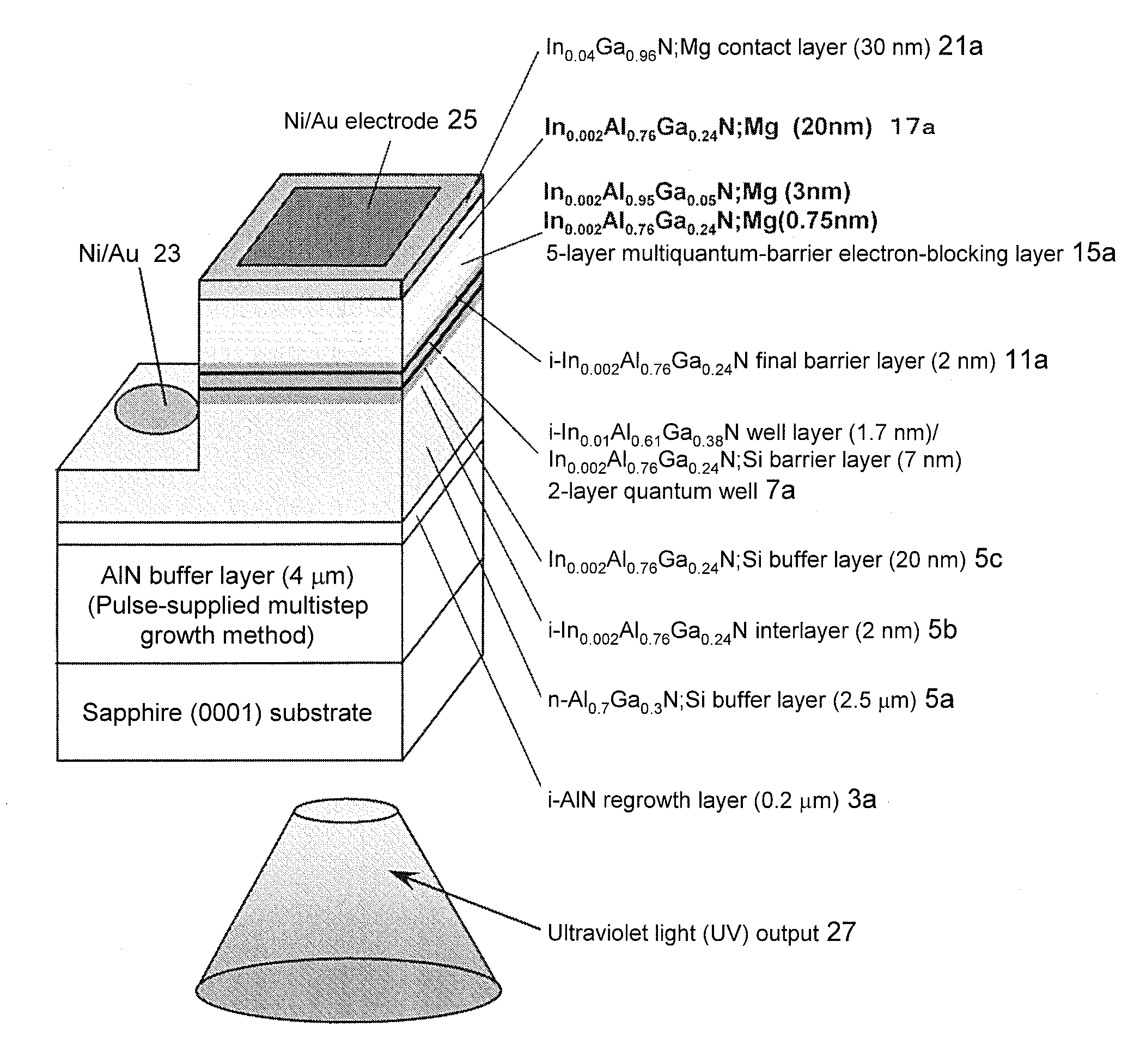
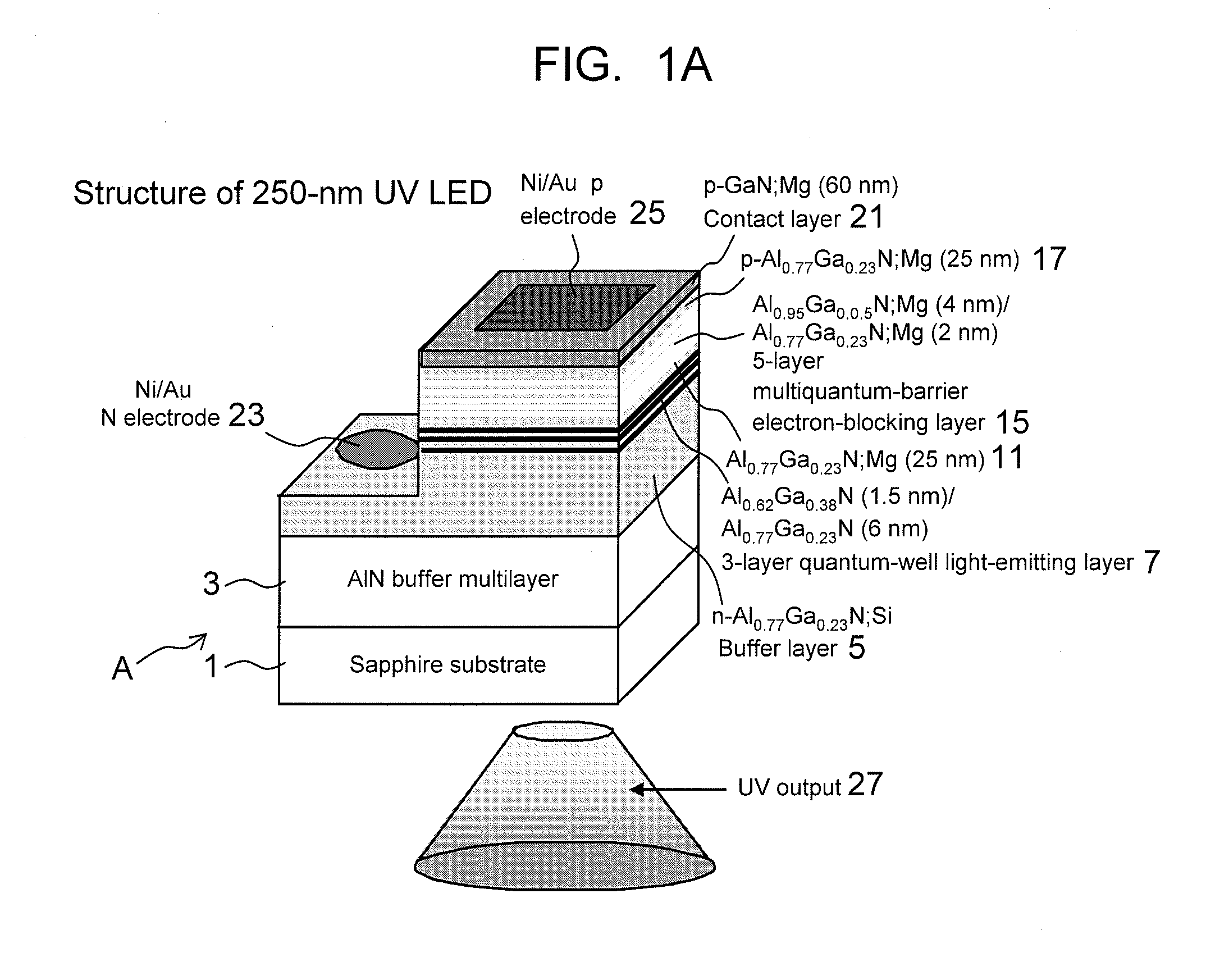
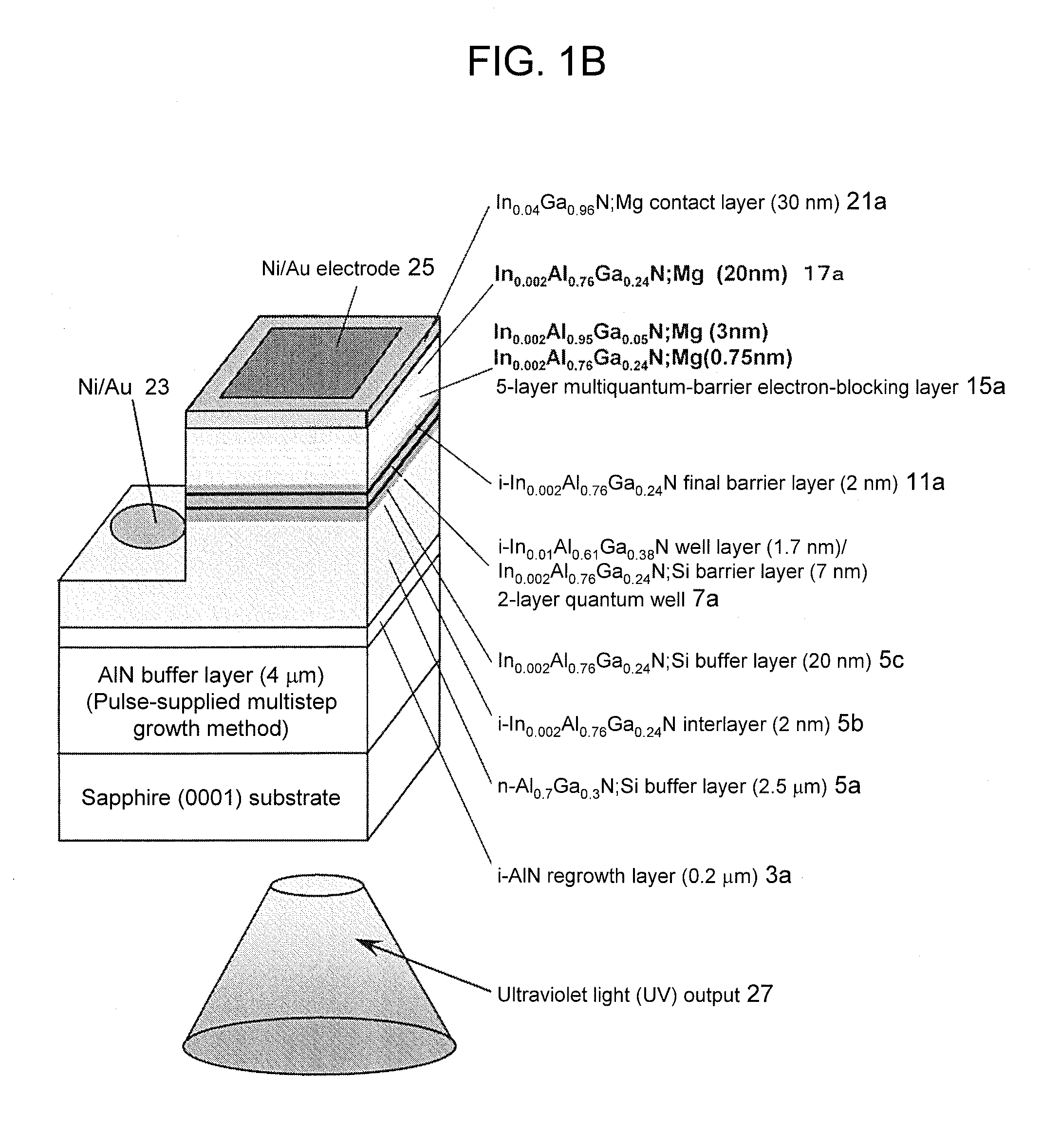
An Al0.95Ga0.05N:Mg (25 nm) single electron barrier can stop electrons having energy levels lower than the barrier height. Meanwhile, a 5-layer Al0.95Ga0.05N (4 nm) / Al0.77Ga0.23N (2 nm) MQB has quantum-mechanical effects so as to stop electrons having energy levels higher than the barrier height. Thus, electrons having energy levels higher than the barrier height can be blocked by making use of multiquantum MQB effects upon electrons. The present inventors found that the use of an MQB allows blocking of electrons having higher energy levels than those blocked using an SQB. In particular, for InAlGaN-based ultraviolet elements, AlGaN having the composition similar to that of AlN is used; however, it is difficult to realize a barrier having the barrier height exceeding that of AlN. Therefore, MQB effects are very important. Accordingly, it becomes possible to provide element technology for further improving deep UV light emission intensity using, as a light-emitting layer material, an AlGaInN-based material and, in particular, an AlGaN-based material.

Description

TECHNICAL FIELD[0001]The present invention relates to nitride semiconductor light-emitting element technology and particularly relates to high-efficiency technology for AlGaN deep-ultraviolet (UV) light-emitting elements with an MQB and the like.BACKGROUND ART[0002]In recent years, nitride semiconductors containing nitrogen as a group V element have been in the limelight in the field of semiconductor light-emitting elements utilizing pn junction, such as light-emitting diodes (LEDs) and laser diodes (LDs), and have been researched and developed. The nitride semiconductors such as AlN, GaN, and InN are direct transition semiconductors. Moreover, nitride semiconductors of ternary mixed crystal type or quaternary mixed crystal type can emit light from infrared light to deep UV light by appropriately setting composition to vary a band gap. In particular, since the UV range is an unexplored light range, further research and development of such nitride semiconductors have been expected.[0...

Claims


Application Information

Patent Timeline
Patent Type & Authority Applications(United States)
IPC IPC(8): H01L33/06H01L33/14
CPCH01L33/04H01L33/32H01L33/06H01L33/12
Inventor HIRAYAMA, HIDEKI
Owner RIKEN
Learn More