
Aerial spraying apparatus

a technology of spraying nozzles and spraying tubes, which is applied in the direction of electric spraying nozzles, spray neutralization, burners, etc., can solve the problems of reducing the effect of spraying,

Inactive Publication Date: 2013-03-21
JOHNSON AIRSPRAY
View PDF4 Cites 7 Cited by
  • Summary
  • Abstract
  • Description
  • Claims
  • Application Information

AI Technical Summary

Benefits of technology

The present invention concerns an aerial spraying apparatus that includes a non-conductive nozzle with a charging electrode for inducing an electrostatic charge on the spray being emitted from the nozzle. The charging electrode is positioned near the spray tip of the nozzle and is in electrical communication with a dc power supply. The apparatus is designed to produce a hollow cone spray. The technical effect of the invention is to enhance the efficiency of the spraying apparatus by inducing an electrostatic charge onto the liquid spray, resulting in a more consistent and accurate spray, with improved control over the spray direction and volume.

Problems solved by technology

Using such extremely high voltages to induce an electrostatic charge onto the spray has its inherent risks, including the possibility of inducing a high potential onto the aircraft in the event of equipment malfunction which could have deleterious effects, possibly fatal, when the pilot attempts to land.

Method used


Image

  • Aerial spraying apparatus
  • Aerial spraying apparatus
  • Aerial spraying apparatus

Examples


Embodiment Construction

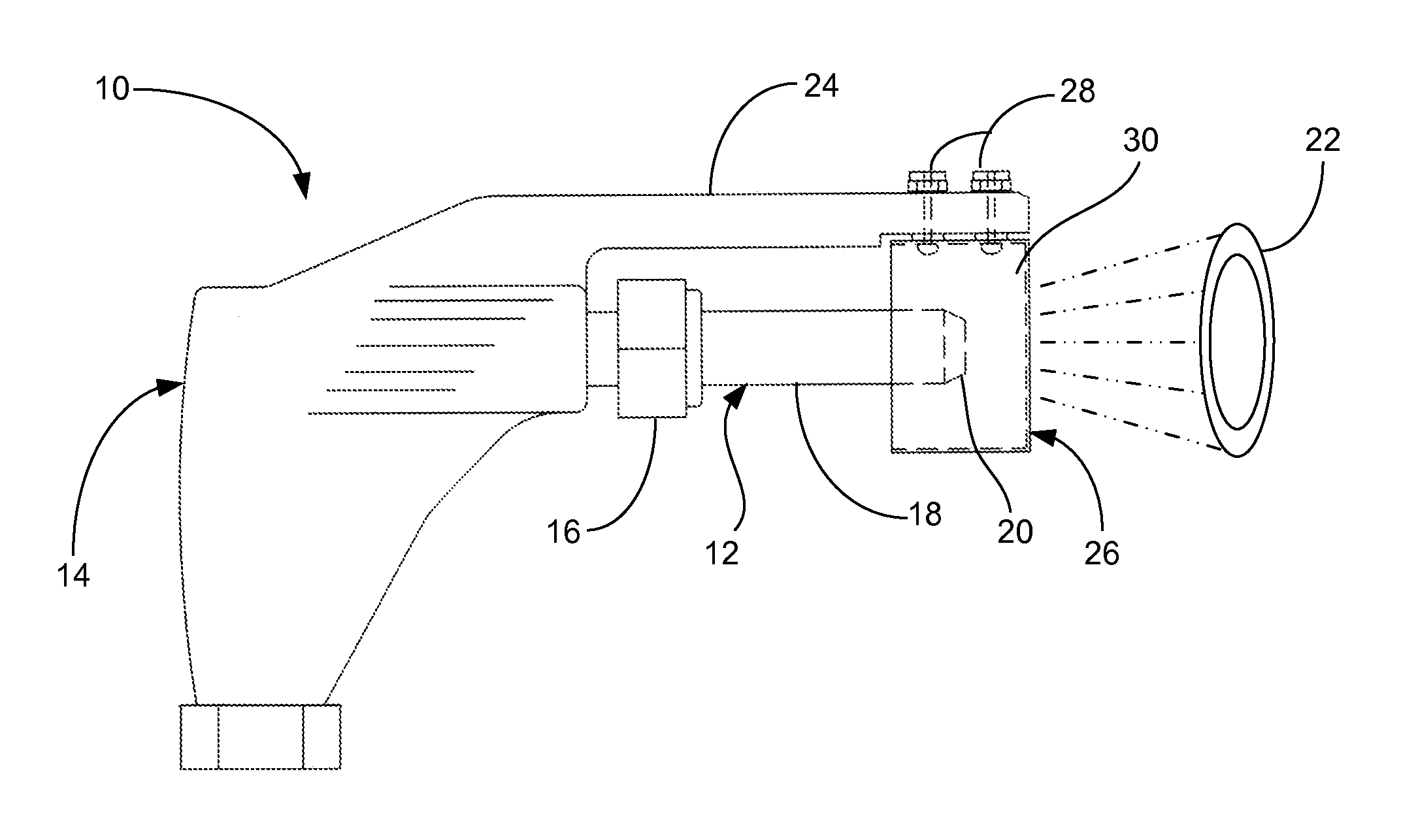
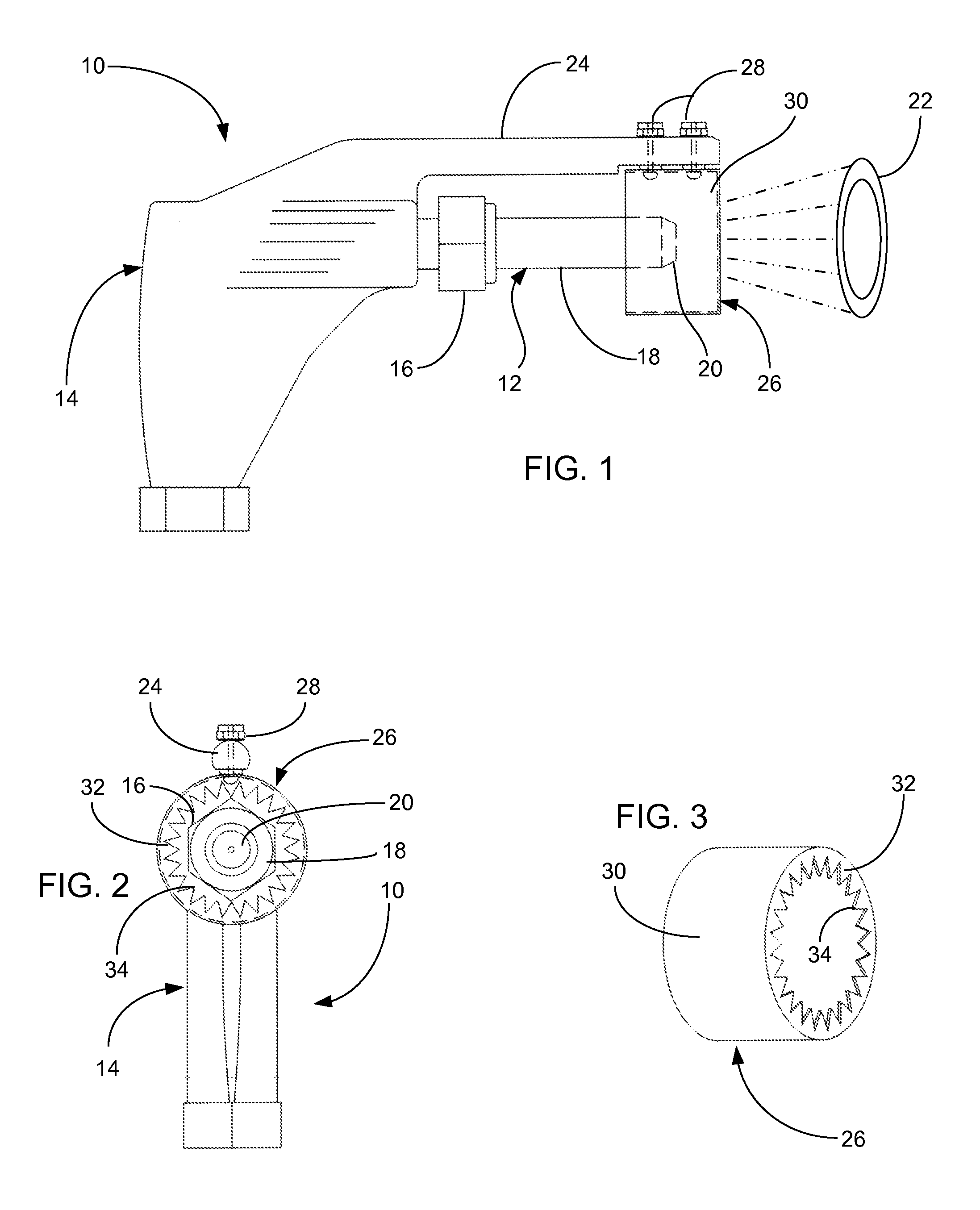
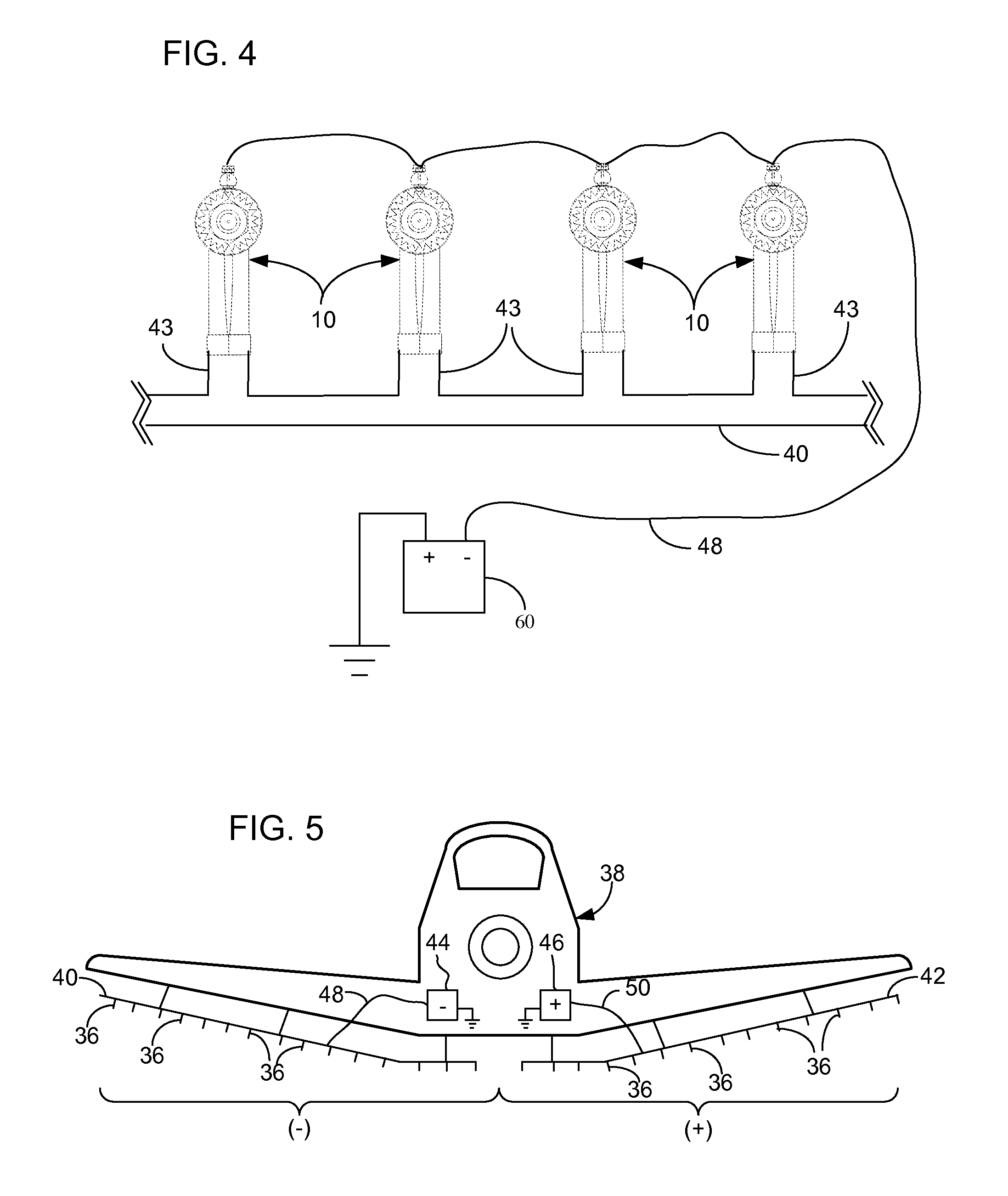
[0013]An aerial spraying apparatus in accordance with the present invention is generally indicated at 10 in FIG. 1. The apparatus 10 generally comprises a nozzle portion 12 connectable to a body portion 14 by a threaded fastener 16. Both the nozzle portion 12 and the body portion 14 are preferably constructed of a substantially non-conductive material, including for example, synthetic plastics such as polystyrene (PS), polyvinyl chloride (PVC), polyethylene terephthalate (PET), polytetrafluoroethylene (PTFE), high-density polyethylene (HDPE), low-density polyethylene (LDPE), and polypropylene (PP). However, those skilled in the art will easily recognize that other non-conductive materials are well within the scope of the present invention as well. The nozzle portion 12 includes a hollow rod 18 constructed from the non-conductive material, approximately 4.5 cm in length and between 1 and 1.5 cm in diameter. Embedded within the hollow rod 18, a spray tip 20 is included for producing a...


PUM


Abstract

An apparatus for spraying and inducing an electrostatic charge upon a liquid in excess of 0.8 millicoloumb / kilogram is connectable to a boom fitted to a vehicle, such as an aircraft, having a dc power supply. The apparatus comprises a nozzle constructed from a substantially non-conductive material and includes a spray tip designed to provide a hollow conical spray pattern. A support member extends from the nozzle and supports a charging electrode for inducing an electrostatic charge upon the liquid sprayed through the nozzle. The charging electrode attaches to the support member and is electrically connectable to the dc power supply. The charging electrode includes a cylindrical portion and a plurality of corona discharge members extending inwardly from a distal end of the cylindrical portion adjacent to the spray tip. The charging electrode is positioned to permit the hollow conical spray pattern to pass unhindered therethrough.

Description

CROSS-REFERENCE TO RELATED APPLICATION(S)[0001]This application claims the benefit of similarly entitled U.S. Provisional Patent Application No. 61 / 536,724, filed on 20 Sep. 2011, which is hereby incorporated herein by reference.BACKGROUND OF THE INVENTION[0002]The present invention is generally directed at spraying nozzles and systems for use in aerial sprayers or crop dusters. More specifically, the present invention includes an aerial spraying nozzle for inducing an electrostatic charge upon a sprayed liquid.[0003]Aerial spraying has long been used as a means of applying herbicides, pesticides, fungicides and other forms of treatments to crops in the agriculture, horticulture and forestry industries. Aerial spraying is typically performed by modifying an aircraft to include a liquid reservoir in fluid communication with a plurality of nozzles held in place by one or more booms attached to the aircraft. The spray itself is usually formed by pumping a chemical liquid mixture contai...

Claims


Application Information

Patent Timeline
IPC IPC(8): B05B5/043
CPCB05B5/043B05B1/06B64D1/18B05B5/0533B05B5/085B05B5/003
Inventor MASSEY, GEORGE N.
Owner JOHNSON AIRSPRAY
Learn More