
Temperature control with induced airflow

Inactive Publication Date: 2006-06-01
RANCO OF DELAWARE
View PDF38 Cites 46 Cited by
  • Summary
  • Abstract
  • Description
  • Claims
  • Application Information

AI Technical Summary

Benefits of technology

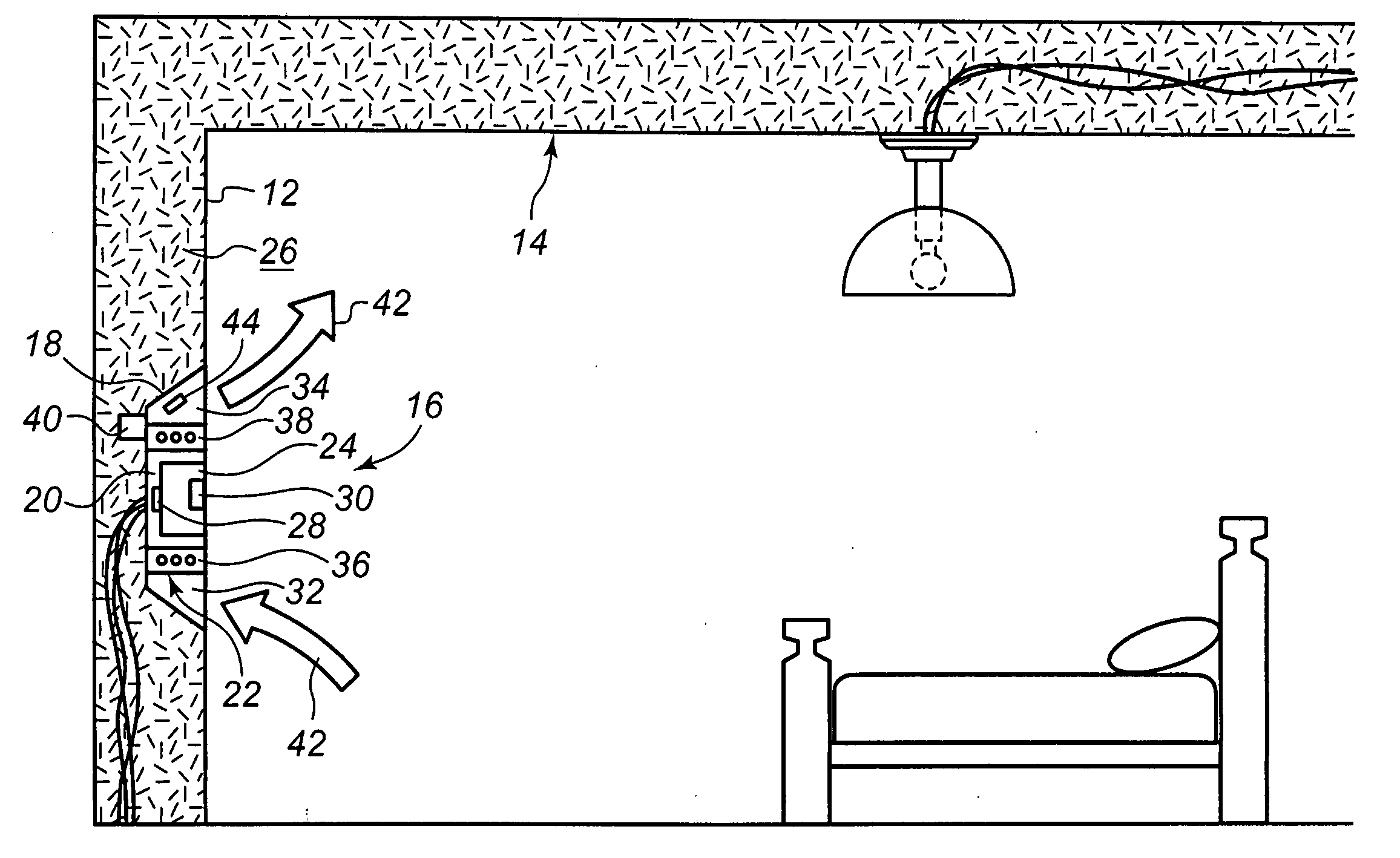
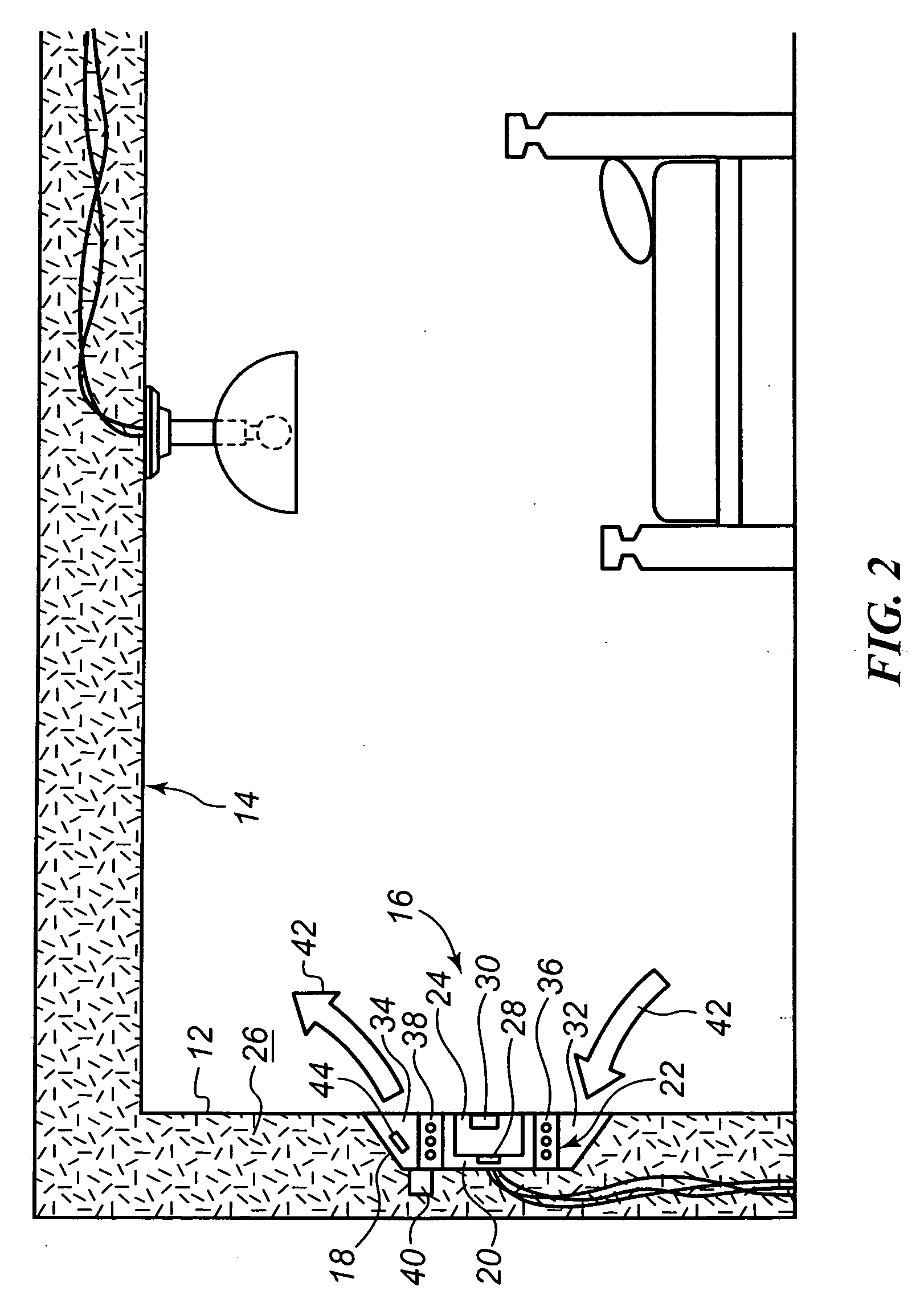
[0009] The invention provides a new and improved thermostat that accurately determines the actual ambient temperature of the living space by inducing airflow through the thermostat. The induced airflow also exhausts any self-heated air and / or residual warm air within the enclosure. The invention also provides a new and improved thermostat that may be mounted flush with a surface of a wall.

Problems solved by technology

One of the issues that a modern wall thermostat faces is correlating a temperature sensed by an internal temperature sensor (e.g., a thermistor) to an actual ambient temperature of an environment.
If the sensed temperature is very different than the actual ambient temperature, the thermostat will not control a heating ventilation and air conditioning (HVAC) system in the most desirable or efficient manner.
Unfortunately, this task often presents significant challenges.
Therefore, any heat retained by the thermostat may be sensed by, and may undesirably influence, the internal temperature sensor.
If enough heat is produced, the internal temperature sensor may be adversely affected such that the device is not able to provide a correct temperature reading.
In addition, the position and / or location where the conventional thermostat can be mounted is often limited due to the operational requirements of the thermostat.
As those skilled in the art will appreciate, air movement near the wall due to convection is poor (i.e., the closer that air gets to the wall, the more static the movement of that air becomes).
As such, the temperature sensed by the thermostat and used to instruct the HVAC might not be accurate relative to the ambient temperature.

Method used


Image

  • Temperature control with induced airflow
  • Temperature control with induced airflow
  • Temperature control with induced airflow

Examples


Embodiment Construction

[0018] Referring now to FIG. 2, a thermostat 16 constructed in accordance with the teachings of the present invention is illustrated. The thermostat 16 comprises a body 18, a passage 20, and at least one corona discharge apparatus 22. The body 14 is preferably constructed of a material such as steel, plastic, and the like. In a preferred embodiment as shown in FIG. 2, the body 14 is configured to be mounted within the wall 12 of the structure 14 such that the front face 24 of the thermostat 16 is planar with an exterior surface 26 of the wall. In other words, the thermostat 16 is flush mounted in the wall 12. The body 14 generally houses at least one sensor 28, one or more control components 30, and a passage 20.

[0019] The sensor 28 is able to sense one or more parameters of the environment within the structure 14 such as, for example, a temperature, a humidity level, and the like. Preferably, the sensor 28 is disposed within, adjacent to, and / or in close proximity to the passage 2...


PUM


Abstract

A thermostat comprising a body, a passage, and at least one corona discharge apparatus is provided. The passage passes through the body and extends between an inlet and an outlet. The corona discharge apparatus is positioned within the passage to draw air into the passage through the inlet and to expel the fluid through the outlet such that the thermostat is able to sense the actual ambient air within the structure within which it is mounted without having to rely on free rise convection of the air. As such, the thermostat is able to be flush mounted in a wall or other structure.

Description

[0001] This patent application claims the benefit of U.S. Provisional Patent Application No. 60 / 632,318, filed Nov. 30, 2004, the teachings and disclosure of which are hereby incorporated in their entireties by reference thereto.FIELD OF THE INVENTION [0002] This invention generally relates to a thermostat and, more particularly, to air flow through the thermostat. BACKGROUND OF THE INVENTION [0003] One of the issues that a modern wall thermostat faces is correlating a temperature sensed by an internal temperature sensor (e.g., a thermistor) to an actual ambient temperature of an environment. If the sensed temperature is very different than the actual ambient temperature, the thermostat will not control a heating ventilation and air conditioning (HVAC) system in the most desirable or efficient manner. Therefore, ensuring that the sensed temperature is the same as, or very nearly the same as, the ambient temperature in a thermostatically controlled environment is important. Unfortuna...

Claims


Application Information

Patent Timeline
IPC IPC(8): G05D23/12F24F3/14F24F7/00
CPCF24F11/0012F24F11/30F24F2110/10F24F11/52F24F11/88
Inventor ASHWORTH, NICHOLAS
Owner RANCO OF DELAWARE
Learn More