Charging device, imaging cartridge and image forming apparatus having charging device
a charging device and imaging cartridge technology, applied in the direction of electrographic process apparatus, instruments, corona discharge, etc., can solve the problems of inability to improve the charging efficiency to a degree capable of higher resolution, higher speed and further miniaturization that can be required for the apparatus for the future, etc., to achieve improved charging efficiency, high resolution, and high precision
- Summary
- Abstract
- Description
- Claims
- Application Information
AI Technical Summary
Benefits of technology
Problems solved by technology
Method used
Image

Examples
first embodiment
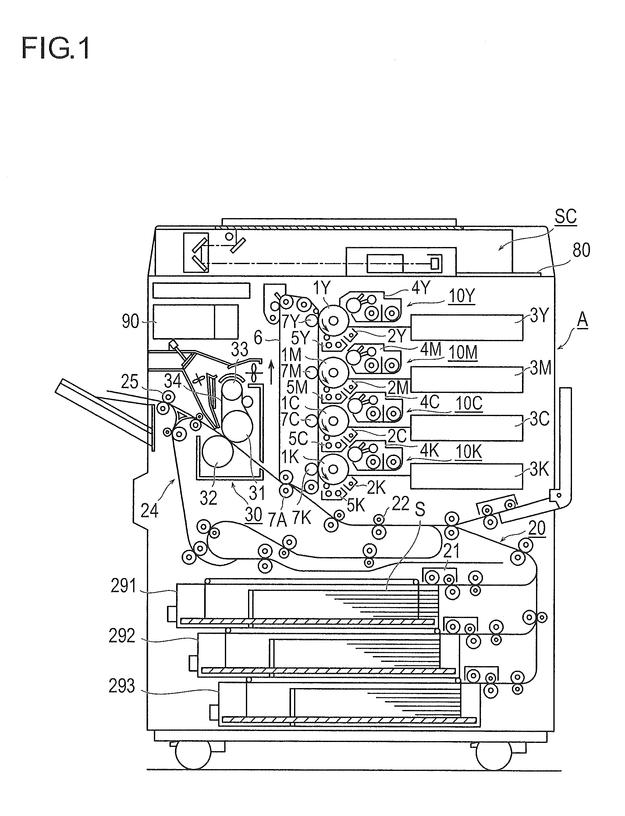
[0028]FIG. 1 is a diagram that describes an image forming apparatus according to a first embodiment of the present invention.
[0029]The image forming apparatus A is referred to as a tandem type color image forming apparatus and performs the color image formation using four sets of image forming parts.
[0030]An image of an original document mounted on an original document table is scanned and exposed by an optical system of a scanning exposure unit of an image scanning unit SC and is read by a line image sensor. Image information signal subjected to a photoelectric conversion is subjected to an analog processing, an A / D conversion, a shading correction, an image compression processing etc. in an image processing part (not shown), and then is input to an optical writing part of the image forming part.
[0031]Four sets of image forming part include an image forming part 10Y forming a yellow (Y) color image, an image forming part 10M forming a magenta (M) color image, an image forming part ...
second embodiment
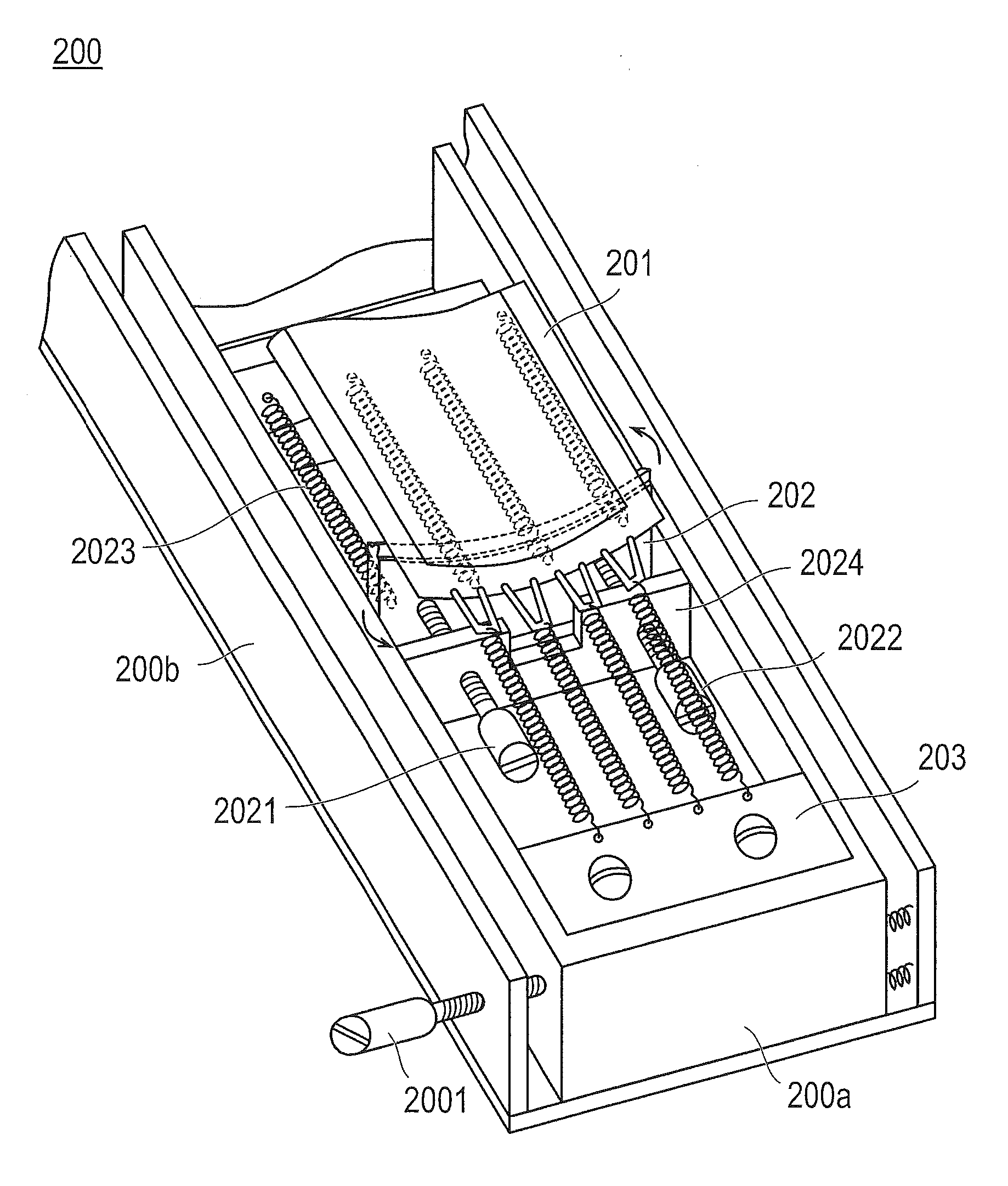
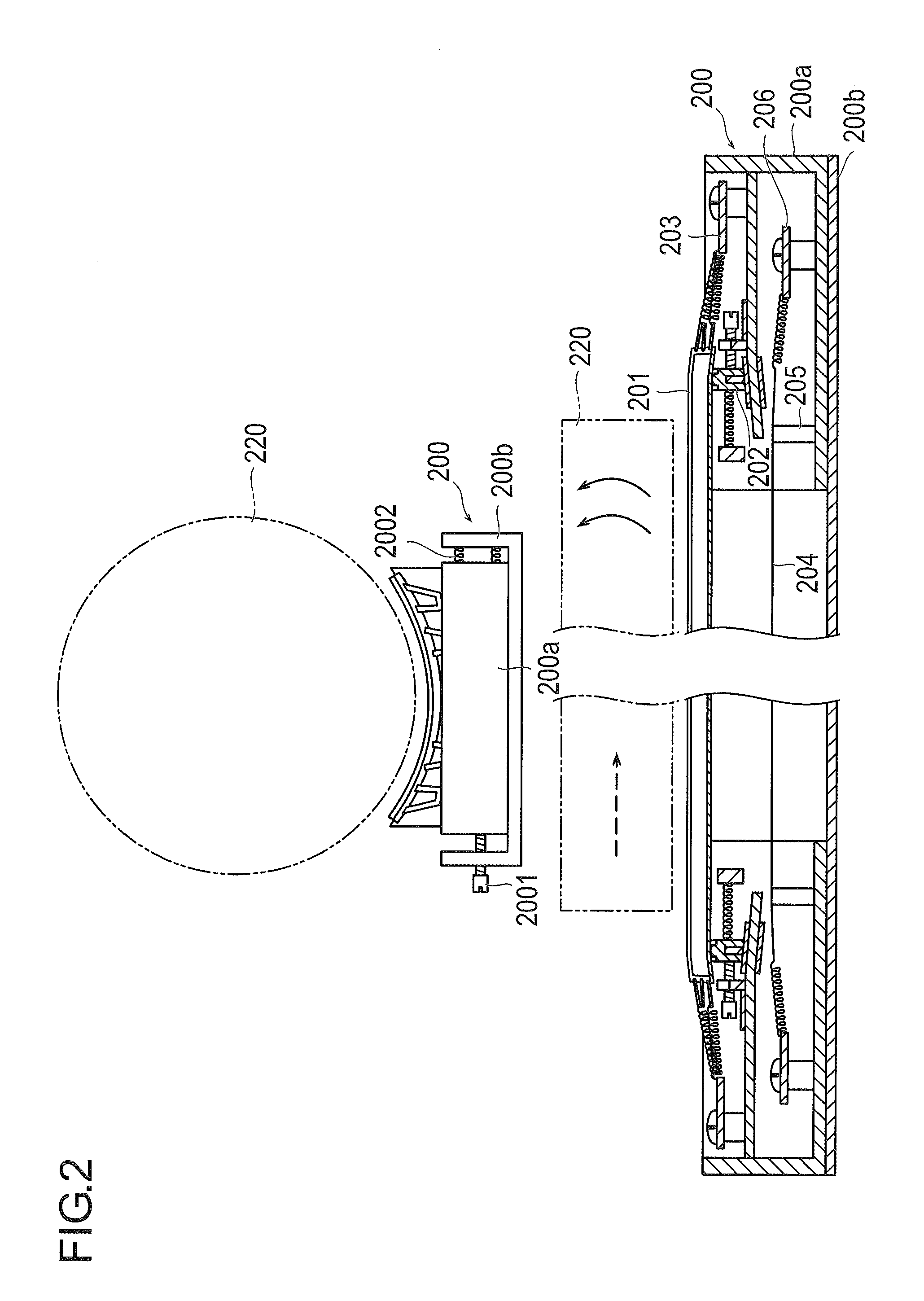
[0070]FIG. 7 is a front view and a perspective view that shows a carrying member and a plate spring of a charging device according to a second embodiment of the present invention. FIG. 8 is a cross-sectional view that shows a part of the charging device according to the present embodiment.
[0071]The present embodiment is different from the first embodiment in the following point. That is, in the first embodiment, by rotating the carrying member constituted by a fixed shape member having curvature, the curvature of the portion carrying the grid is changed. Meanwhile, in the present embodiment, an elastic body having curvature is used in the carrying member and is elastically deformed by external force to change the curvature of the portion carrying the grid. Furthermore, in the first embodiment, by causing the carrying member to slide on the slope surface, the relative distance between the carrying member and the photoconductive drum is changed. Meanwhile, in the present embodiment, b...
third embodiment
[0084]FIG. 9 is a perspective view that shows a carrying member and a curvature guide surface of a charging device according to a third embodiment of the present invention. FIG. 10 is a cross-sectional view that shows a part of the charging device according to the present embodiment.
[0085]The present embodiment is different from the first embodiment in the next point. That is, in the first embodiment, by rotating the carrying member constituted by a fixed form member having curvature, the curvature of the portion carrying the grid is changed. Meanwhile, in the present embodiment, by causing the carrying member having curvature to slide while being pressed against the curvature guide surface which the curvature is gradually changed, the carrying member is deformed to change the curvature of the portion carrying the grid. Furthermore, in the first embodiment, by causing the carrying member to slide on the slope surface, the relative distance between the carrying member and the photoco...
PUM
 Abstract
Description
Claims
Application Information
 - R&D
- Intellectual Property
- Life Sciences
- Materials
- Tech Scout
- Unparalleled Data Quality
- Higher Quality Content
- 60% Fewer Hallucinations
Browse by: Latest US Patents, China's latest patents, Technical Efficacy Thesaurus, Application Domain, Technology Topic, Popular Technical Reports.
© 2025 PatSnap. All rights reserved.Legal|Privacy policy|Modern Slavery Act Transparency Statement|Sitemap|About US| Contact US: help@patsnap.com