Machining tool and cutting head for the machining tool

Active Publication Date: 2013-02-28
KENNAMETAL INC
View PDF14 Cites 11 Cited by
  • Summary
  • Abstract
  • Description
  • Claims
  • Application Information

AI Technical Summary

Benefits of technology

The invention simplifies the design of a machining tool by improving its coupling region, making it easier to fit in the holder without aids and securely centered. The use of an external thread and cylindrical thread in the cutting head and holder, respectively, enhances force transmission and wear resistance. The coupling region requires minimal space and is suitable for small shank cutting heads. The external thread is a maximum of 50% of the clamping cone's length, which contributes to the tool's spatial economy. The use of a coarse thread allows for quicker clamping and avoids over-tight bracing, while a fine thread enables smoother and more precise setting of the screwed coupling.

Problems solved by technology

A disadvantage of this tool is the introduction of forces.
On account of the conical form of the thread, the latter tends to keep tightening itself during the milling machining and thereby increase the forces acting in the screwed coupling.

Method used


Image

  • Machining tool and cutting head for the machining tool
  • Machining tool and cutting head for the machining tool
  • Machining tool and cutting head for the machining tool

Examples


Embodiment Construction

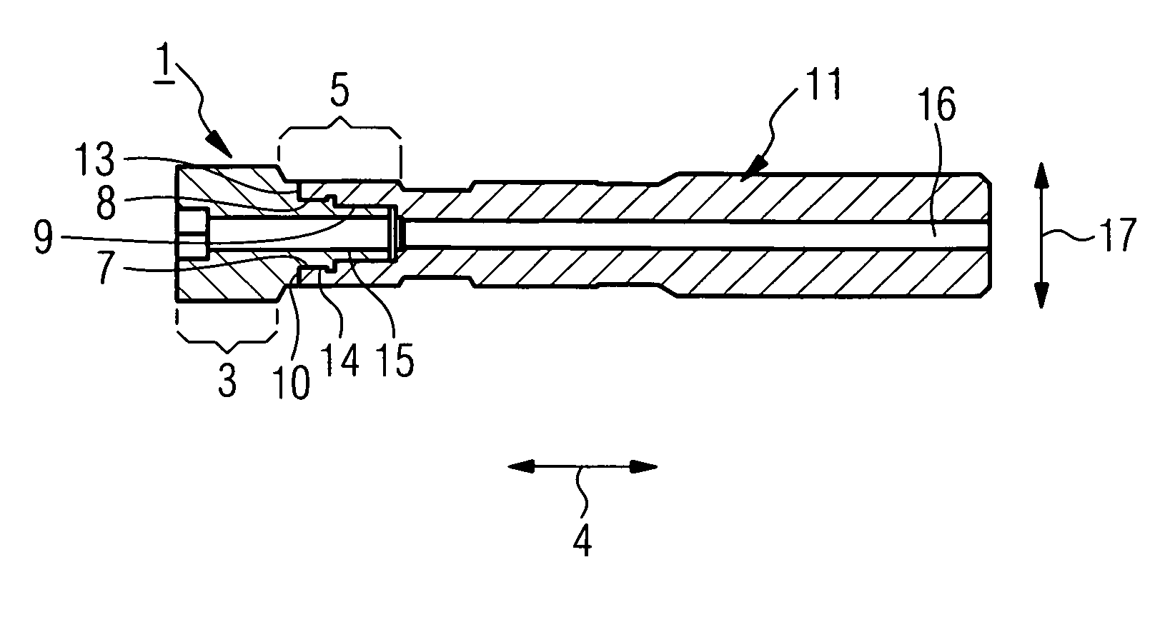
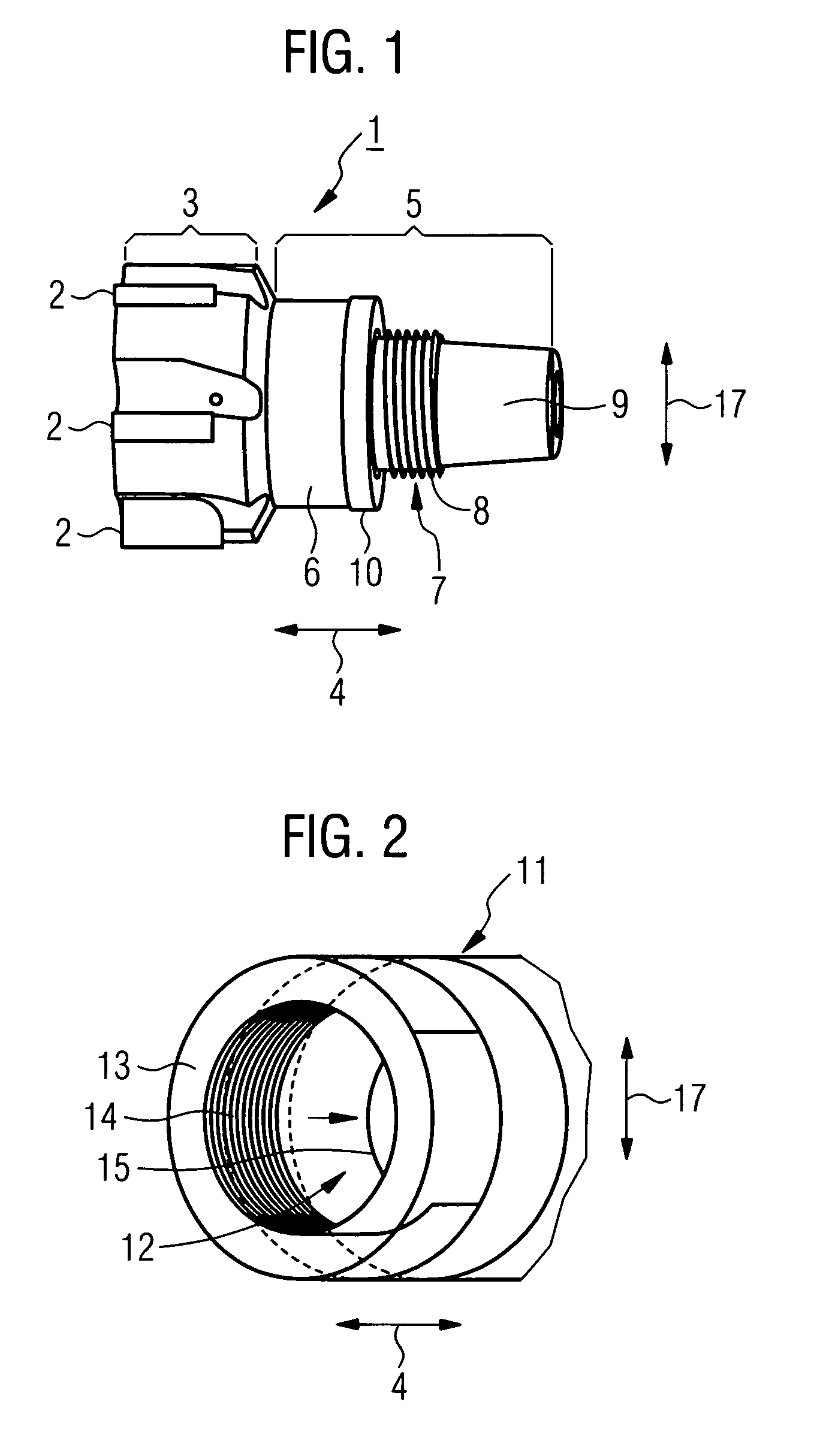
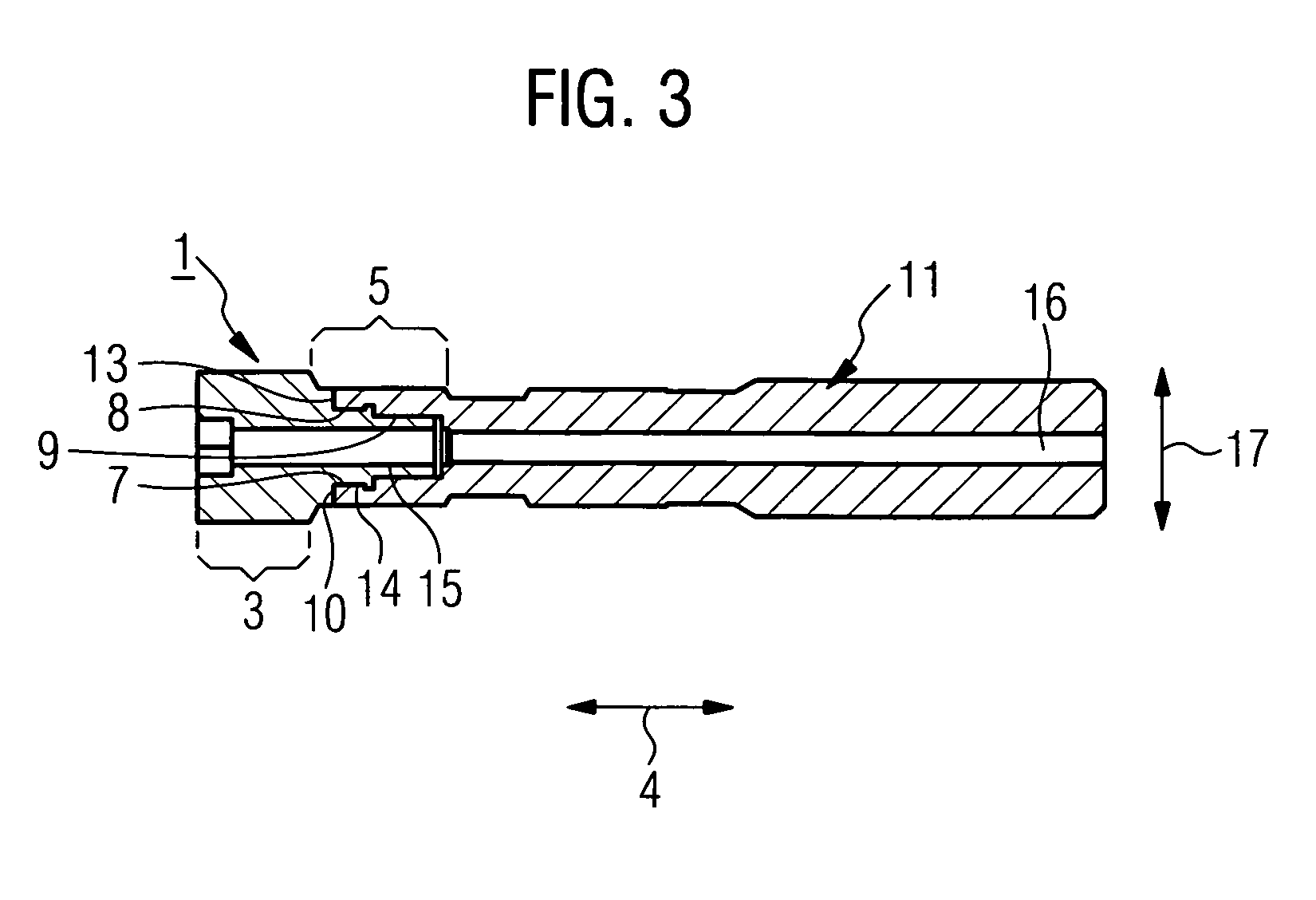
[0022]The cutting head 1 consists of a cutting-edge region 3, bearing a number of cutting edges 2, and of a coupling region 5, adjoining the cutting-edge region 3 in the axial direction 4.

[0023]The coupling region 5 is for its part made up of the flat collar 6, the cylindrical thread carrier 7 and the clamping cone 9. The flat collar 6 in this case adjoins the cutting-edge region 3 in the axial direction 4. Projecting in the axial direction 4 from the end face of the flat collar 6 that is facing away from the cutting-edge region 3 in the axial direction 4 there is the cylindrical thread carrier 7. Formed into the outer lateral surface of the thread carrier 7 is the external thread 8. The thread carrier 7 is in turn adjoined in the axial direction 4 by the clamping cone 9. The outer periphery of the end face of the flat collar 6 that is facing away from the cutting-edge region 3 forms the flat contact area 10. The flat contact area 10 consequently runs in the manner of a ring around ...


PUM

PropertyMeasurementUnit
Lengthaaaaaaaaaa
Areaaaaaaaaaaa
Hardnessaaaaaaaaaa

Abstract

A machining tool includes a holder and a cutting head which can be screwed into the holder. The cutting head includes a cutting-edge region and a coupling region. The coupling region includes a flat contact area facing the holder, a cylindrical thread carrier with an external thread adjoining the flat contact area, and a clamping cone adjoining the thread carrier. The holder includes a planar counter-contact area disposed adjacent the flat contact area of the coupling region, a cylindrical internal thread adjoining the planar counter-contact area, and a hollow-conical cone contact area next to the internal thread.

Description

BACKGROUND OF THE INVENTION[0001]The invention relates to a machining tool with a holder and with a cutting head which can be screwed into the holder and relates to such a cutting head. The cutting head for its part comprises a cutting-edge region and a coupling region. Such a cutting head that can be screwed into a holder is known, for example, from U.S. 2001 / 0041089 A1.[0002]On account of the present-day precision production methods for cutting tools, in particular cutting heads, it is possible to produce a cutting head without laborious finishing operations, in particular grinding work on the cutting-edge region, being required at the end of the production process. For reasons of cost, it is desired on the one hand to dispense with clamping aids, for example clamping pins, in the coupling region, and on the other hand to complete the cutting tool without having to carry out remachining in the coupling region of the cutting head to make it fit into the holder.[0003]The periodical ...

Claims


Application Information

Patent Timeline
IPC IPC(8): B23B31/11B23B27/00B23C5/26
CPCB23B31/1107B23B31/1122B23C5/10B23C2210/02Y10T407/19Y10T407/1906Y10T407/1946Y10T407/1908Y10T408/907B23C2210/03
Inventor SCHUFFENHAUER, MICHAELXYLANDER, RENE
Owner KENNAMETAL INC
Why Eureka
Try Eureka