Flexible conductive single wire
a flexible, wire technology, applied in the direction of conductors, conductive layers on insulating supports, therapy, etc., can solve the problems of plastic deformation fatigue, metal fatigue reduction, and often not to an acceptable level, and achieve the same radiopaque results, short processing time, and high radiopacity
- Summary
- Abstract
- Description
- Claims
- Application Information
AI Technical Summary
Benefits of technology
Problems solved by technology
Method used
Image
Examples
example 1
Plasma Deposition Method
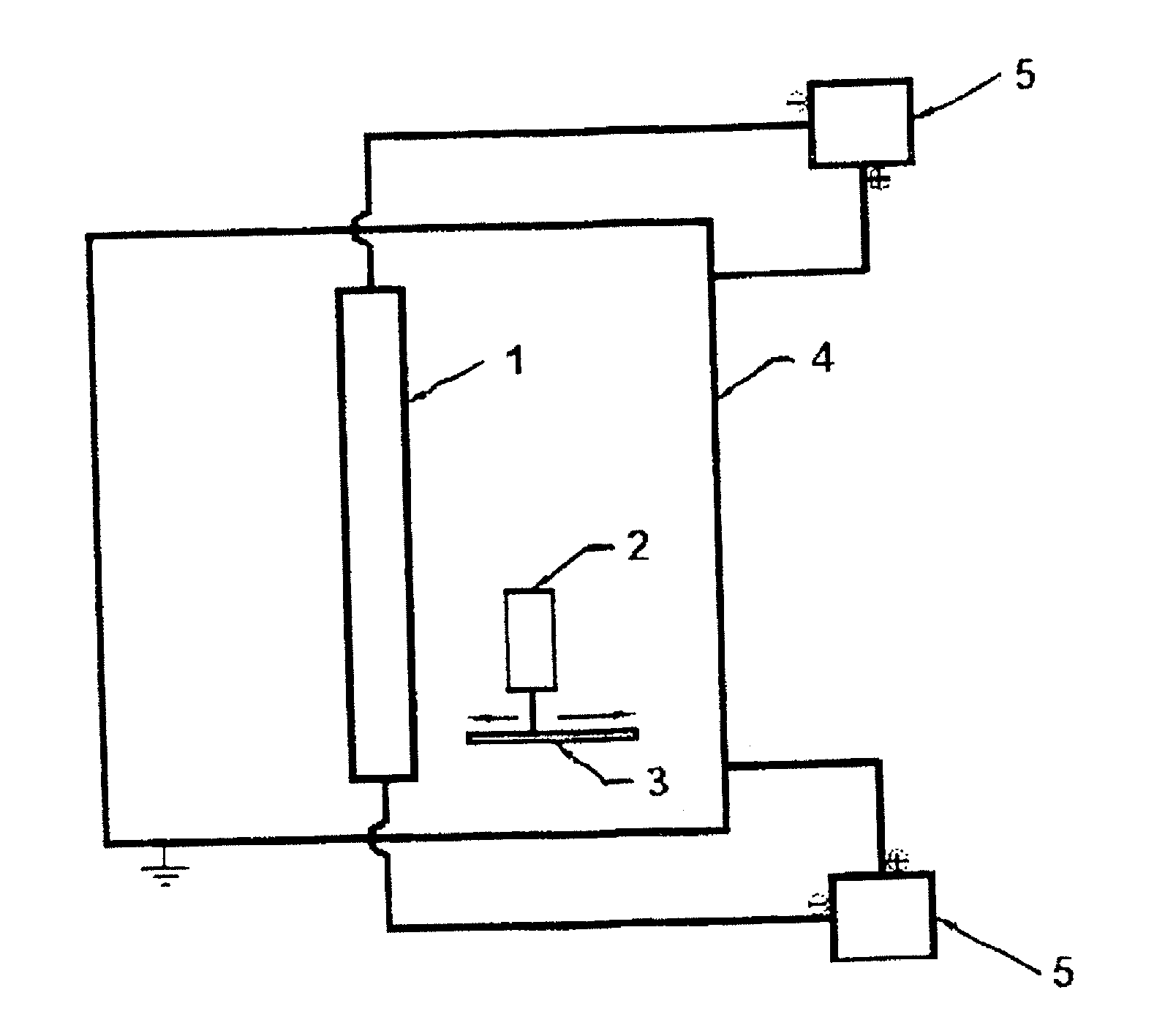
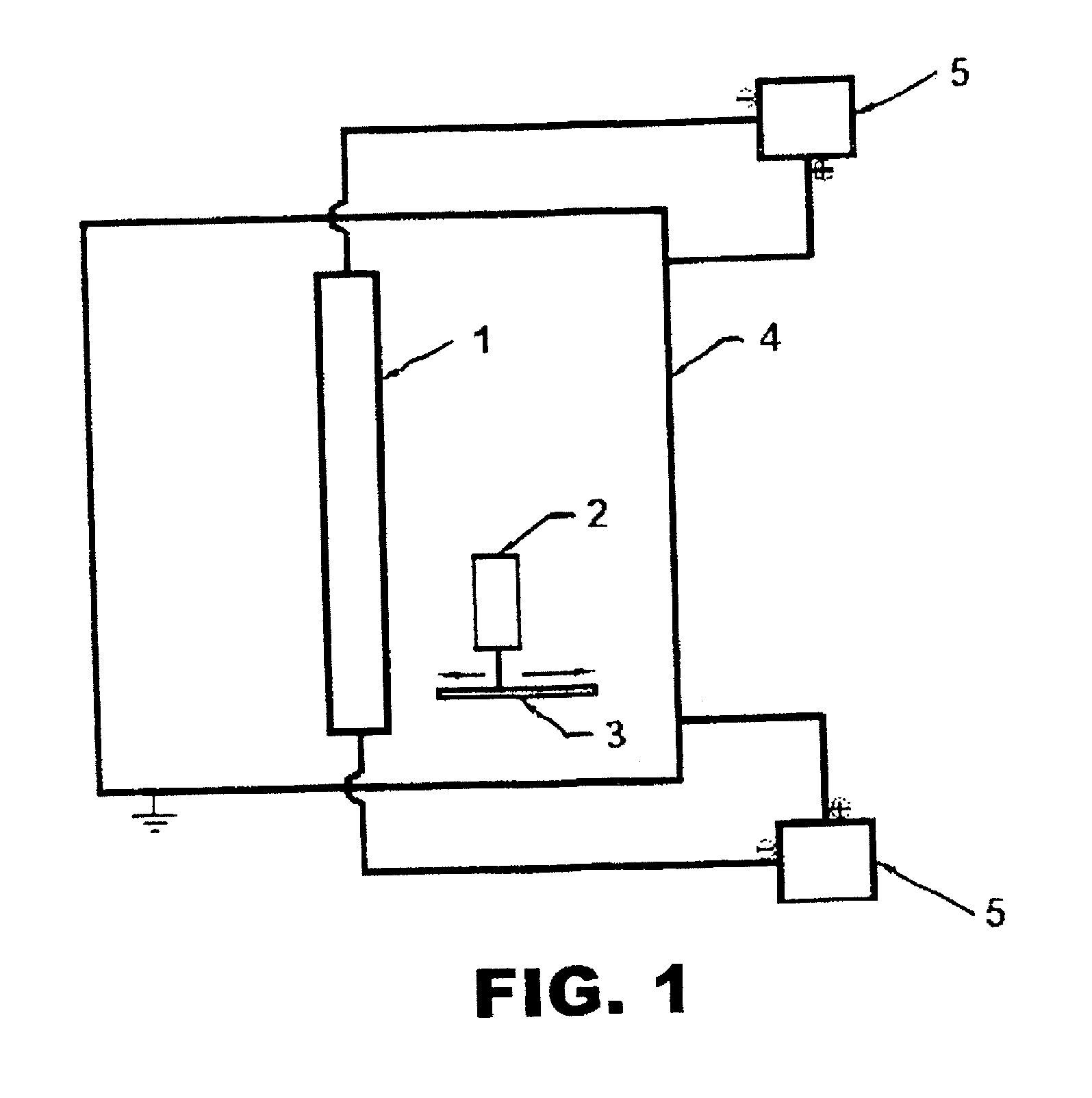
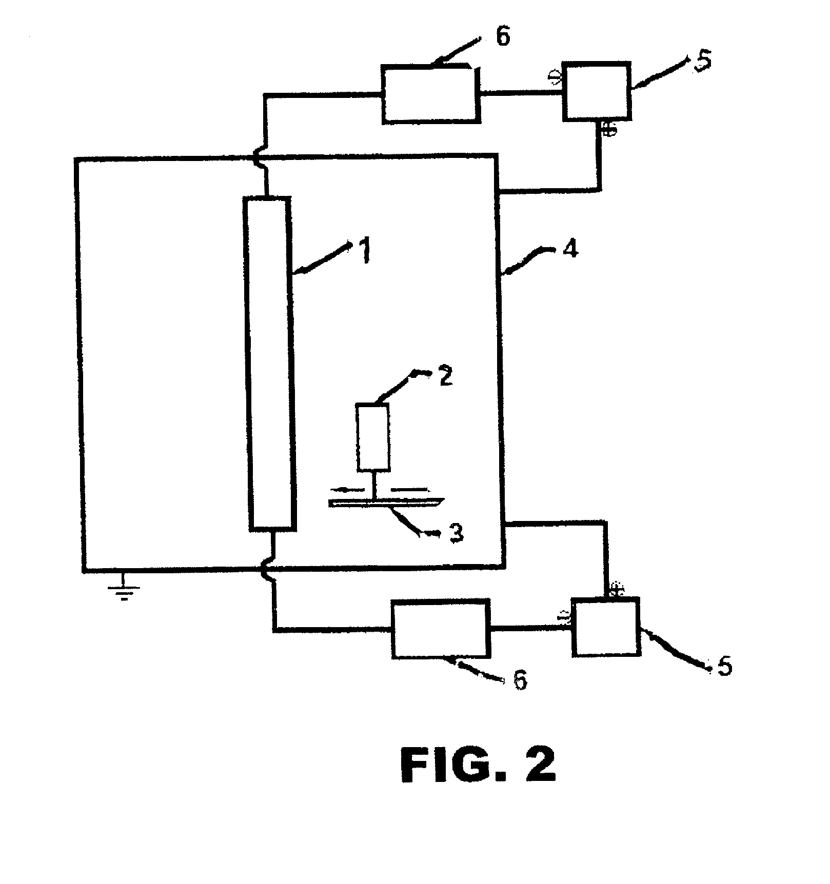
[0071]The modified Ionic Plasma Deposition method utilizes a controlled cathodic arc discharge on a target material to create highly energized plasma. The method differs from normal ion plasma depositions in several ways, including precise control of arc speed. This allows for faster movement, creating fewer macro particles without the use of sensors or filters, or slower movement, creating a greater amount and larger macro particles. It also gives the option of mixing the two modes to create a moderate amount of particles, or creating a near macro-free coating followed by a macro-dense coating. Alternatively, macroparticle density can also be controlled by adjusting movement of the substrate with respect to distance from the target during deposition.
[0072]Several nonmetal substrates have been coated with highly radiopaque coatings, including PTFE, ePTFE, polypropylene, polyester, PEEK, UHMWPE, silicone, polyimide, acrylates and ABS. The coatings deposited by...
example 2
[0077]Samples of catheters were coated with 5, 10, 15, and 20 microns of radiopaque gold markers and tested in a conventional cath-lab system. A standard radiological procedure indicated an x-ray intensity of 60 kV and for large patients 90 kV was used. Under normal conditions (60 kV), the 10, 15, and 20 micron samples were visible. Using 90 kV, the 5 micron sample in addition to the 10, 15, and 20 micron samples were visible. The testing was performed with the prepared samples and no other biomass. The appearance of a typical gold film surface is shown in FIG. 3. The initially deposited gold has a smooth surface (FIG. 4) with few if any macroparticles.
example 3
Thin Metal Coating on PEEK Spinal Implant
[0078]A spinal implant constructed of PEEK was coated with a 5 micron thick coating of gold using the IPD method described in example 1. The coating had an average of 100 nm macro-particles densely distributed over the coating surface. A typical macroparticle distribution of 90,000 cm2 is shown in FIG. 3. The implant was masked such that when coated, only a limited area of the implant, typically not visible under x-ray irradiation, would be visible.
[0079]The coated portion of the implant was viewed with a fluoroscope at 60 kV and 90 kV with no other biomass. The fluoroscope imaged implant markings were highly visible.
PUM
| Property | Measurement | Unit |
|---|---|---|
| Length | aaaaa | aaaaa |
| Length | aaaaa | aaaaa |
| Diameter | aaaaa | aaaaa |
Abstract
Description
Claims
Application Information
 - R&D
- Intellectual Property
- Life Sciences
- Materials
- Tech Scout
- Unparalleled Data Quality
- Higher Quality Content
- 60% Fewer Hallucinations
Browse by: Latest US Patents, China's latest patents, Technical Efficacy Thesaurus, Application Domain, Technology Topic, Popular Technical Reports.
© 2025 PatSnap. All rights reserved.Legal|Privacy policy|Modern Slavery Act Transparency Statement|Sitemap|About US| Contact US: help@patsnap.com


