
Intelligent backhaul radio and antenna system

a backhaul radio and antenna system technology, applied in the field of data networking, can solve the problems of imposing further demands on the antenna design, high path loss exponent of wireless channel, time-domain delay spread, etc., and achieve the effect of reducing the minimum angular width of the antenna pattern, reducing the cost of antenna installation, and reducing the cost of installation

Active Publication Date: 2013-02-21
COMS IP HLDG LLC
View PDF0 Cites 285 Cited by
  • Summary
  • Abstract
  • Description
  • Claims
  • Application Information

AI Technical Summary

Benefits of technology

The patent describes a way to improve data communication in urban areas using a special type of wireless technology called IBR. This technology uses multiple antennas to overcome challenges like line-of-sight visibility and high path loss. An advantage of this technology is that it can use a single antenna design for both polarization diversity and angular beam diversity, which helps to achieve high-capacity data communication. This patent also explains how polarization diversity and angular beam diversity work together to improve the performance of the IBR technology.

Problems solved by technology

The resulting wireless channel features high path loss exponents, time-domain delay spread, and wide angular-spread of incoming power (i.e spatial Rayleigh fading).
In addition, some embodiments of the IBR rely on two-stream spatial multiplexing, which places further demands on the antenna design.

Method used


Image

  • Intelligent backhaul radio and antenna system
  • Intelligent backhaul radio and antenna system
  • Intelligent backhaul radio and antenna system

Examples


Embodiment Construction

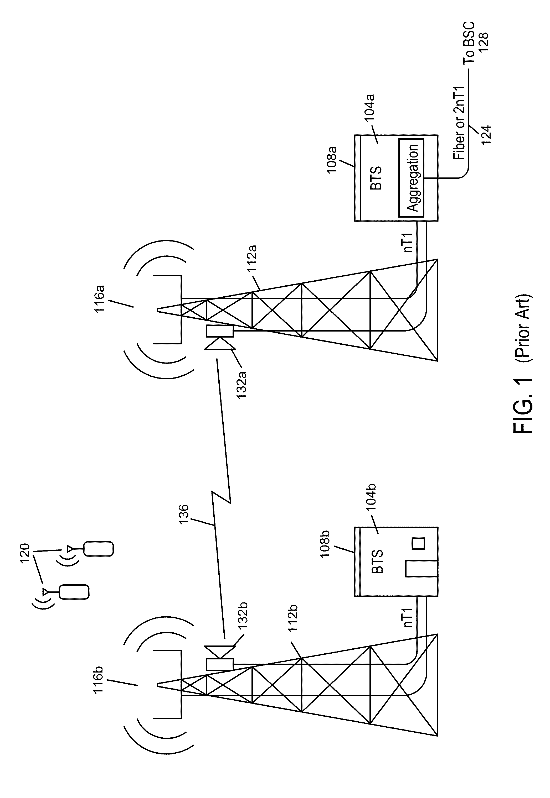
[0139]FIG. 5 illustrates deployment of intelligent backhaul radios (IBRs) in accordance with an embodiment of the invention. As shown in FIG. 5, the IBRs 500 are deployable at street level with obstructions such as trees 504, hills 508, buildings 512, etc. between them. The IBRs 500 are also deployable in configurations that include point to multipoint (PMP), as shown in FIG. 5, as well as point to point (PTP). In other words, each IBR 500 may communicate with more than one other IBR 500.

[0140]For 3G and especially for 4th Generation (4G), cellular network infrastructure is more commonly deployed using “microcells” or “picocells.” In this cellular network infrastructure, compact base stations (eNodeBs) 516 are situated outdoors at street level. When such eNodeBs 516 are unable to connect locally to optical fiber or a copper wireline of sufficient data bandwidth, then a wireless connection to a fiberpoint of presence” (POP) requires obstructed LOS capabilities, as described herein....


PUM


Abstract

A intelligent backhaul radio have an advanced antenna system for use in PTP or PMP topologies. The antenna system provides a significant diversity benefit. Antenna configurations are disclosed that provide for increased transmitter to receiver isolation, adaptive polarization and MIMO transmission equalization. Adaptive optimization of transmission parameters based upon side information provided in the form of metric feedback from a far end receiver utilizing the antenna system is also disclosed.

Description

BACKGROUND[0001]1. Field[0002]The present disclosure relates generally to data networking and in particular to a backhaul radio for connecting remote edge access networks to core networks and an associated antenna system.[0003]2. Related Art[0004]Data networking traffic has grown at approximately 100% per year for over 20 years and continues to grow at this pace. Only transport over optical fiber has shown the ability to keep pace with this ever-increasing data networking demand for core data networks. While deployment of optical fiber to an edge of the core data network would be advantageous from a network performance perspective, it is often impractical to connect all high bandwidth data networking points with optical fiber at all times. Instead, connections to remote edge access networks from core networks are often achieved with wireless radio, wireless infrared, and / or copper wireline technologies.[0005]Radio, especially in the form of cellular or wireless local area network (W...

Claims


Application Information

Patent Timeline
IPC IPC(8): H01Q21/24H01Q3/00
CPCH01Q21/24H04B7/10H04L5/0007H04L25/03828H04L27/2601H04L27/2636H01Q1/246H01Q21/29H01Q25/00H01Q25/005H04B10/25H04L1/0001H04L1/004H04L1/18H04B7/0408H04B7/0695H04B7/088H04W88/08H04B1/401H04B1/50H04L27/01H01Q25/001H01Q1/48H01Q1/50H01Q21/062H01Q21/064H01Q21/065
Inventor LEA, DAVID ANDREW G.NEGUS, KEVIN J.PROCTOR, JR., JAMES A.
Owner COMS IP HLDG LLC
Learn More