
Dynamic resource allocation for transaction requests issued by initiator devices to recipient devices

a technology of initiator device and recipient device, which is applied in the field of data processing system, can solve the problems of increasing the buffer size of the buffer for storing pending transactions on the recipient device, the difficulty of bounding the latency of each transaction request, and the associated overhead of continual trying, so as to reduce the overhead of area, increase the latency of some transaction requests, and simple yet efficient

Active Publication Date: 2013-02-14
ARM LTD
View PDF9 Cites 8 Cited by
  • Summary
  • Abstract
  • Description
  • Claims
  • Application Information

AI Technical Summary

Benefits of technology

The present invention addresses a problem where a recipient device may not have enough space to store transaction requests, causing delays and increased latency. The invention proposes a solution where a recipient device reserves storage space for future transactions and sends a credit grant to an initiator device that had a previously rejected transaction request. The initiator device can then re-issue the rejected transaction request with a guarantee that it will be accepted. This allows for prioritization of performance critical transactions and ensures that unused credit grants are tracked.

Problems solved by technology

A disadvantage of this is that it is difficult to bound the latency for each transaction request as one can continually try and not succeed.
Furthermore, the continual trying has an overhead of time, power and bandwidth associated with it.
A drawback of this is that as systems become larger, in order to provide all initiators with credits for each recipient, the buffers for storing pending transactions on the recipients need to become larger and larger.

Method used


Image

  • Dynamic resource allocation for transaction requests issued by initiator devices to recipient devices
  • Dynamic resource allocation for transaction requests issued by initiator devices to recipient devices
  • Dynamic resource allocation for transaction requests issued by initiator devices to recipient devices

Examples


Embodiment Construction

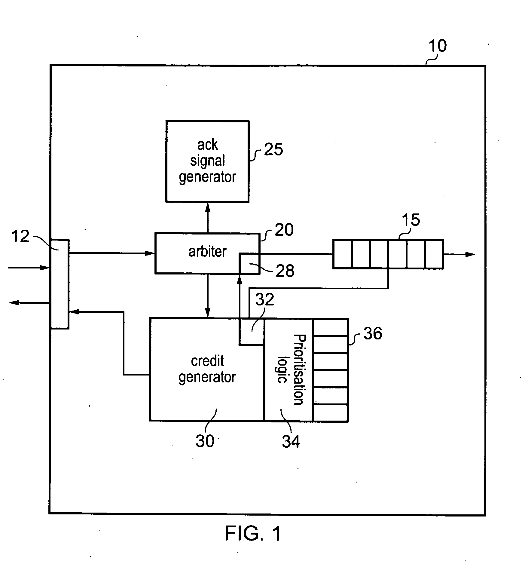
[0052]FIG. 1 shows a recipient device 10 according to an embodiment of the present invention. This recipient device may typically be a slave in a system such as, a coherency controller or an input / output bridge.

[0053]This recipient device receives transaction requests at port 12 from initiator devices sent over an interconnect. Recipient device 10 comprises a buffer 15 for storing pending transaction requests that have been received prior to them being executed by the recipient device. Thus, in response to receipt of a transaction request the recipient device 10 will accept the transaction request and store it in buffer 15 provided there is a storage location available. Whether or not there is a storage location available is determined by arbiter 20.

[0054]The pending transaction requests are stored in buffer 15 until the recipient device can execute them, whereupon the transaction request is evicted from buffer 15. Once the recipient device has executed a pending transaction request...


PUM


Abstract

Initiator devices for generating transaction requests and recipient devices for receiving them are disclosed. The recipient devices accept transaction requests where there is available buffer storage for the transaction request. If there is no storage space available an acknowledgement signal generator generates and outputs a reject acknowledgement signal indicating a request has been received but has not been accepted by the recipient device. A credit generator can reserve at least one available storage location in the buffer and generate a credit grant for an initiator device that sent one of the transaction requests that was not accepted by the recipient device. The credit grant indicates to the initiator device that there is at least one reserved storage location, such that a subsequent transaction request from the initiator device will be accepted by the recipient device. Thus, the initiator device may not transmit the transaction request again until it has received the credit grant, whereupon it may transmit it along with a credit grant indicator such that it is sure that it will be accepted.

Description

BACKGROUND OF THE INVENTION[0001]1. Field of the Invention[0002]The field of the invention relates to data processing systems and in particular, to systems having a number of initiator devices issuing transaction requests to a number of recipient devices and to the allocation of resources within the recipient devices for executing these transaction requests.[0003]2. Description of the Prior Art[0004]Resource allocation for a plurality of initiator devices accessing a plurality of recipient devices in, for example, distributed shared memory needs to be carefully managed to ensure forward progress of each type of transaction request. This has been done in a variety of ways in systems of the prior art, but generally by the use of implicit or explicit resource allocation.[0005]Implicit resource allocation has been done using acknowledgement signals sent from the recipient device and indicating to the initiator device whether the transaction request has been accepted or not. If it has no...

Claims


Application Information

Patent Timeline
Patent Type & Authority Applications(United States)
IPC IPC(8): G06F13/14
CPCG06F13/16G06F13/1605G06F13/364G06F13/161G06F13/1642G06F13/1673
Inventor MANNAVA, PHANINDRA KUMARJALAL, JAMSHEDPRASADH, RAMAMOORTHY GURUFILIPPO, MICHAEL ALANMATHEWSON, BRUCE JAMESMACE, TIMOTHY CHARLES
Owner ARM LTD
Learn More