
System for estimating membrane stress on arbitrary-shaped curvilinear surface based on current configuration data

a technology of configuration data and membrane stress, applied in the field of medical diagnostic systems, can solve the problems of accuracy, foregoing analysis methods, and hardly becoming a practical diagnostic tool in the scene of clinical practi

Active Publication Date: 2013-02-14
WASHIO TAKUMI +4
View PDF4 Cites 2 Cited by
  • Summary
  • Abstract
  • Description
  • Claims
  • Application Information

AI Technical Summary

Benefits of technology

The stress estimating system described in this patent is a method for analyzing the stress in a vascular wall without assuming the shape or axisymmetric nature of the stress. By using a boundary condition that is applied to a modeled vascular wall boundary, a finite element analysis is performed, which allows for the complete separation of the effects of boundary conditions, blood pressure, and other factors. This makes it possible to accurately estimate the stress in the vascular wall without needing information about the material properties of the wall or the shape under no-loaded condition.

Problems solved by technology

However, this diagnostic method using only a representative dimension for evaluating stress of a complex shaped aneurysm includes a problem of accuracy, and cases have been reported where rupture occurred at an aneurysm shape to which operation had not been performed under the decision of the above-mentioned diagnostic method (C.f.
However, the foregoing analysis methods have the following problems generally when applied to the bio-mechanical analysis.
(a) Since it is impossible for measuring the material property parameters of aorta of each individual in vivo, modification of the experimental data conducted in vitro using a typical specimen is needed before the use.
(b) Since it is also impossible for obtaining the shape of aorta under a non-loaded condition from CT images, some analysis must be done to modify the shape which was obtained from a loaded condition or a kind of residual stress must be introduced.
Conventional stress analysis methods caused by the analysis complexity and uncertainty in accordance with above problems will hardly become a practical diagnostic tool in the scene of clinical practice.

Method used


Image

  • System for estimating membrane stress on arbitrary-shaped curvilinear surface based on current configuration data
  • System for estimating membrane stress on arbitrary-shaped curvilinear surface based on current configuration data
  • System for estimating membrane stress on arbitrary-shaped curvilinear surface based on current configuration data

Examples


first embodiment

[0040]The stress estimating system of this invention estimates two-dimensional stress (plane stress assuming all the stresses concerned with thickness direction is zero) from polygon data expressing shape of vascular wall after deformation obtained by a medical image, blood pressure estimated from other medical equipment, and tensile force applied to the vascular wall estimated from the blood pressure.

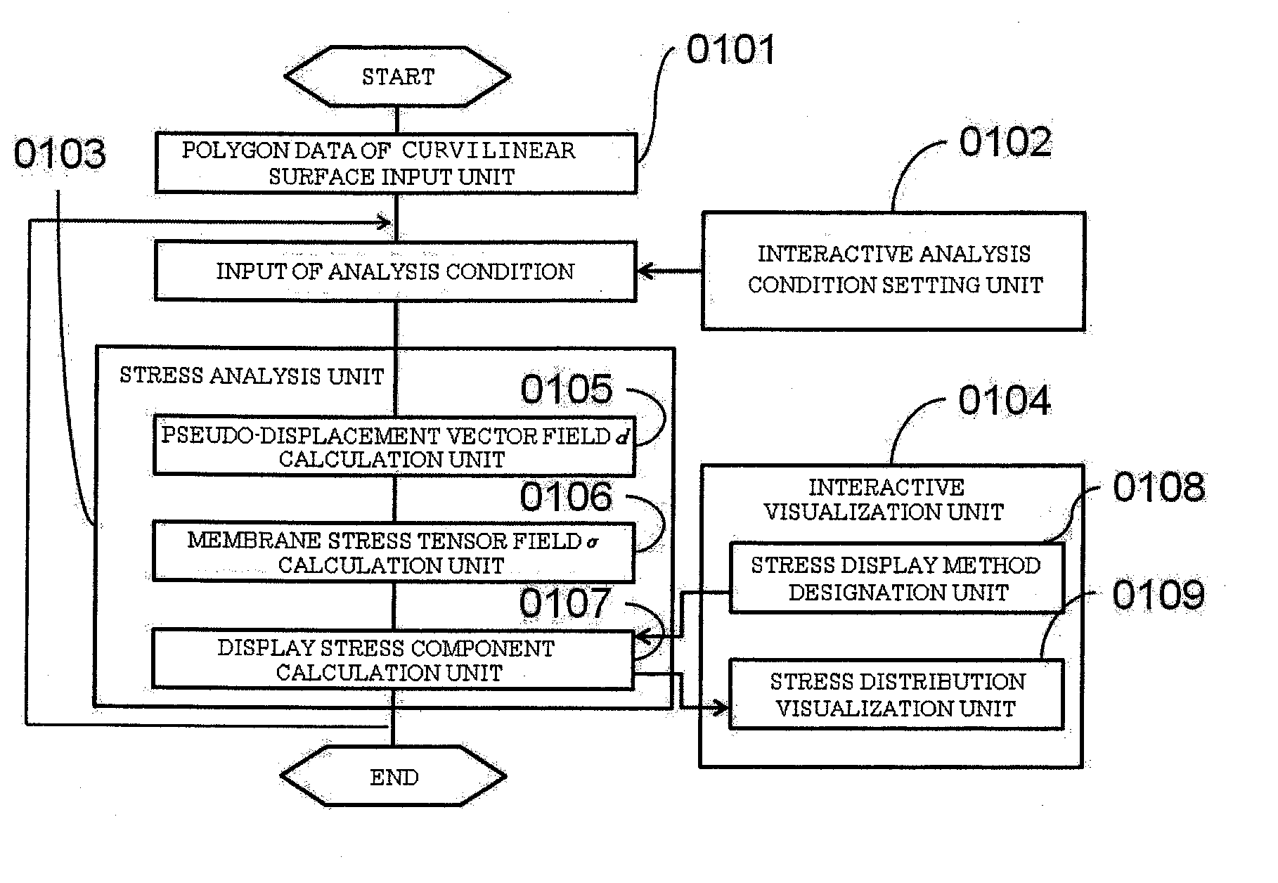
[0041]FIG. 1 shows an embodiment of this invention, and a functional block indicating an essential part of the stress estimating system. From polygon data input unit of curvilinear surface of wall0101, polygon data expressing curvilinear surface of wall is read. Through interactive analysis condition setting unit 0102, a user of this system designates blood pressure, constraint at boundary of curvilinear surface, and the tensile force acts at boundary. In stress analysis unit 0103, the two-dimensional stress on the curvilinear surface is calculated under the given analysis condition, s...

experimental example 1

[0058]In FIG. 17, a first experiment is shown. 1701 is a shape data of aorta vascular wall obtained from multi slice CT. Analysis condition as shown in 1701 is inputted through the interactive analysis condition setting unit 0102. In this practice, blood pressure of 120 mmHg is inputted in the blood pressure input unit 0501, lower end of descending aorta is set as being fixed in the fixed information input unit 0502 as shown in 1702, a uniform axial tensile force of which the total is equal to the product of blood pressure and sectional area of aorta root is set in the traction force input unit 0503 as shown in 1703, and constraint for the components of pseudo-displacement vector perpendicular to axial direction of root is designated at constraint unit and constraint input unit 0504.

[0059]Under the foregoing analysis condition, for the stress tensor calculated in stress analysis unit 0103, at interactive visualization unit 0104, circumferential and axial vectors are inputted, and 17...

experimental example 2

[0060]In FIG. 18, there is disclosed a case where an aneurysm exists in ascending aorta, and obtained result of stress estimation carried out by applying a similar analytic condition as in the experimental example 1 through interactive analysis condition setting unit 0102. In interactive visualization unit 0104, vectors for circumferential and axial direction are inputted, and 1801 shows circumferential stress component and 1802 shows axial stress component, respectively. In the stress analysis system of this invention, stress estimation, even in a case where vascular shape is largely out of axisymmetry due to the existence of aneurysm, can be carried out without problems.


PUM


Abstract

A stress estimating system includes a polygon data input unit of polygon data modeling a vascular wall, an interactive analysis condition setting unit for setting the tensile force acting on the vascular wall boundary, blood pressure and constraint estimated as proper on the boundary, a stress analysis unit for obtaining two-dimensional stress by solving a mechanical equilibrium equation with respect to the membrane stress on a curvilinear surface of the vascular wall under the condition given by the polygon data input unit and the interactive analysis condition setting unit, and an interactive visualization unit for displaying a distribution of a stress component designated by a system user. Without assuming any symmetry for the curvilinear configuration and stress distribution, a complicated stress distribution is estimated only out of the mechanical equilibrium equation with respect to membrane stress.

Description

TECHNICAL FIELD[0001]In a medical diagnostic systems, this invention is concerned with a diagnostic technique for estimating stress distribution on the vascular wall and evaluating its rupture risk based on curvilinear surface shape of vascular wall surrounding the blood domain which is obtained from medical image by diagnostic equipment, such as MRI, CT, ultrasound echo image.BACKGROUND[0002]Aneurysm of aorta and dissection of the aorta are typical diseases of the thoracic aorta, and there is an influential theory that those diseases are caused by aortic wall stress. Especially in relation to aortic aneurysm, magnitude of generated stress and risk of rupture of the aneurysm are considered to be directly related with each other. Decision of whether or not to perform operation has been judged by measuring the diameter of the aneurysm and evaluating the generated stress in the aneurysm based on the Laplace's law (approximation of thin-walled cylindrical shells) (C.f. Non-patent Litera...

Claims


Application Information

Patent Timeline
Patent Type & Authority Applications(United States)
IPC IPC(8): G06F17/10
CPCA61B5/021A61B5/055A61B5/02014A61B8/14G06F17/5018A61B6/03G06F30/23
Inventor WASHIO, TAKUMIHISADA, TOSHIAKINUNOBIKI, EIJIOKADA, JUN-ICHISUGIURA, SEIRYO
Owner WASHIO TAKUMI
Learn More