Methods for sequentially laminating rare earth permanent magnets with suflide-based dielectric layer
a technology of dielectric layer and rare earth permanent magnet, which is applied in the direction of magnetic circuits characterised by magnetic materials, magnetic bodies, manufacturing tools, etc., can solve the problems of adversely affecting the magnetic properties of permanent magnets, and achieve the effects of reducing eddy current losses, sacrificing rare earth, and increasing electrical resistivity
- Summary
- Abstract
- Description
- Claims
- Application Information
AI Technical Summary
Benefits of technology
Problems solved by technology
Method used
Image
Examples
example 1
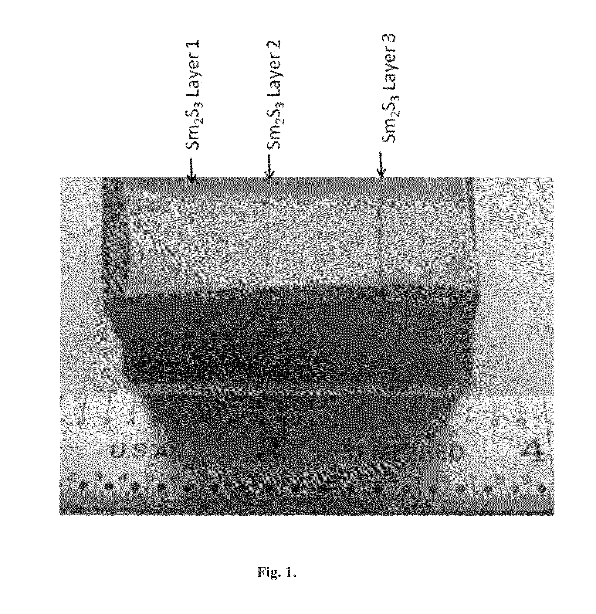
FIGS. 1 and 2
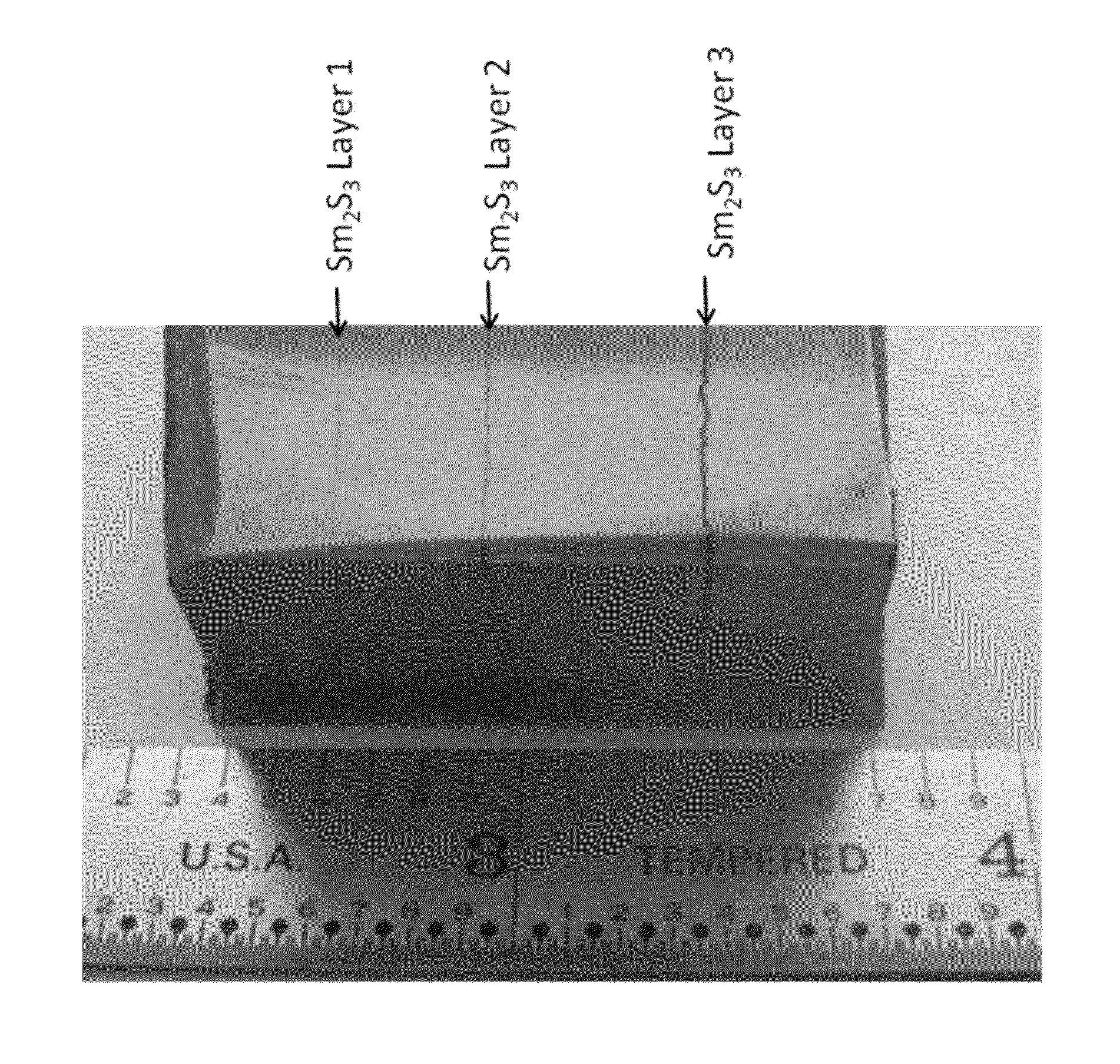
[0156]An anisotropic Sm(Co,Fe,Cu,Zr)z / Sm2S3 sequentially laminated magnet with increased electrical resistivity was synthesized, according to the methods of the present invention, by regular powder metallurgic processes consisting of sintering at from 1200° C. to 1220° C., solution treatment at from 1160° C. to 1180° C. and aging at from 830° C. to 890° C. This step was followed by a slow cooling to 400° C. The sequentially laminated, anisotropic magnet consisting of three sequential Sm(Co,Fe,Cu,Zr)z layers and three sequential Sm2S3 layers, shown in FIG. 1, was produced by a one-step sintering process.
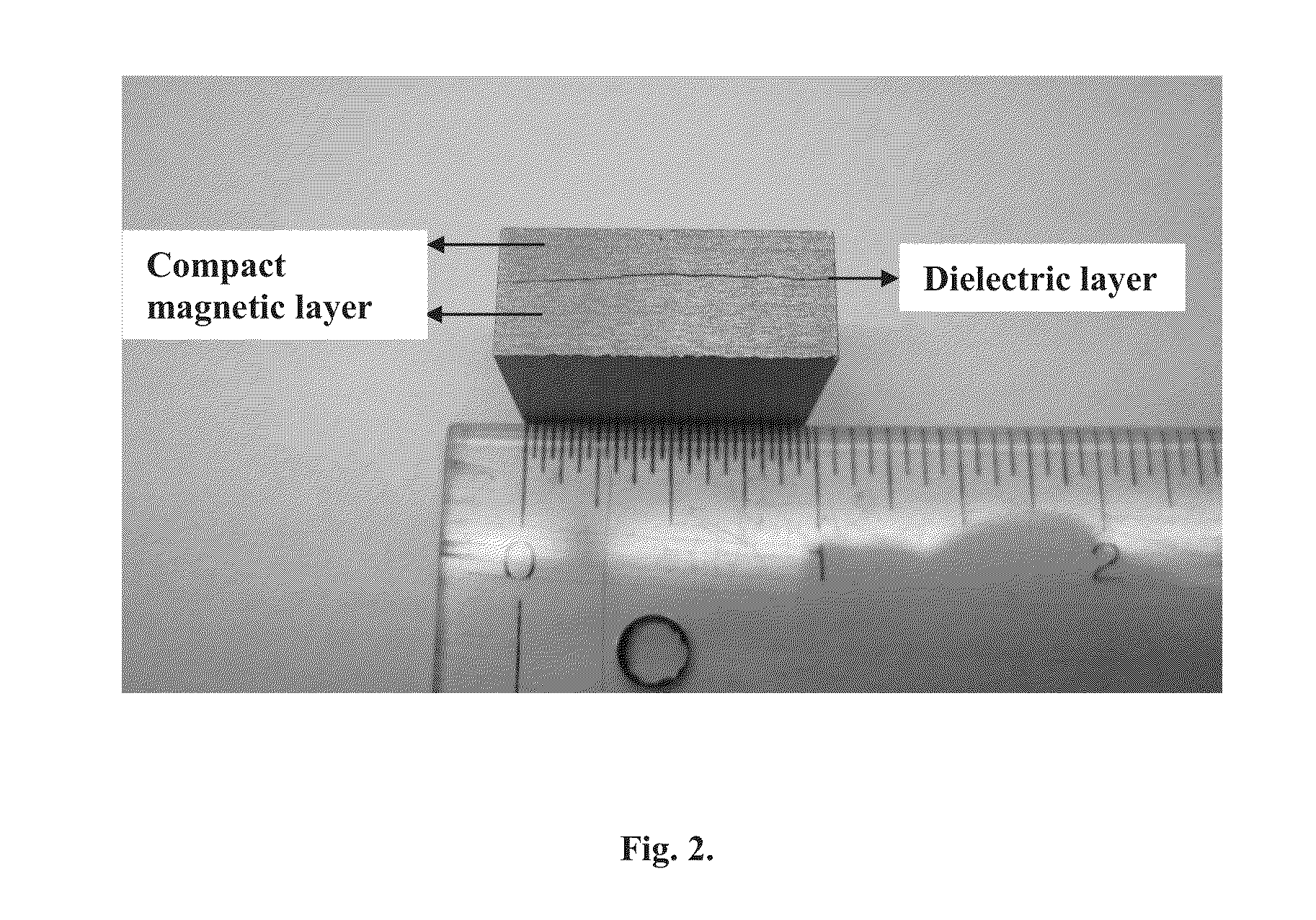
[0157]The photograph set out in FIG. 2 shows the thickness and uniformity of the sulfide-based, dielectric layer of a sequentially laminated anisotropic magnet produced according to the methods of the present invention. In the process of the present invention, this thickness and uniformity of sulfide-based, dielectric layers is controlled by spraying a colloidal solution ...
example 2
FIGS. 3 and 4
[0158]FIG. 3 shows an optical micrograph of a Sm2S3 colloidal layer deposited on a Sm(Co,Fe,Cu,Zr)z sequentially laminated magnet, produced according to the methods of the present invention, after polishing and etching. The Sm2S3 dielectric layer is about 190 μm thick. The magnetic layers and interface diffusion reaction layers separating the sulfide-based, dielectric layer from the permanent magnet layers are clearly shown. The demagnetization curve for this sequentially laminated, permanent magnet, produced according to the methods of the invention compared to conventional non-layered magnets indicates comparable magnetic properties. The magnetic properties of the sequentially laminated Sm(Co,Fe,Cu,Zr)z / Sm2S3 magnet shown in FIG. 3 were reported in FIG. 4, as follows:
[0159]Residual induction: Br=10.516 kG
[0160]Intrinsic coercivity: Hci>24.5 kOe
[0161]Maximum energy product: (BH)max=25.5 MGOe
[0162]The electrical resistivity of this sequentially laminated, rare earth, pe...
example 3
FIG. 5
[0163]FIG. 5 shows an optical micrograph of a Sm2S3 colloidal, dielectric layer deposited on a Sm(Co,Fe,Cu,Zr)z sequentially laminated magnet, produced according to the method of the present invention, after polishing and etching. The Sm2S3 dielectric layer is about 30 μm thick. The magnetic layers and interface diffusion reaction layers separating the sulfide-based, dielectric layer from the permanent magnet layers are clearly shown. The demagnetization curve for this sequentially laminated, permanent magnet produced according to the methods of the invention compared to conventional non-layered magnets indicates comparable magnetic properties. The magnetic properties of the laminated Sm(Co,Fe,Cu,Zr)z / Sm2S3 magnet shown in FIG. 5 were as follows:
[0164]Residual induction: Br=10.73 kG
[0165]Intrinsic coercivity: Hci>24.5 kOe
[0166]Maximum energy product: (BH)max=25.5 MGOe
[0167]The electrical resistivity of this sequentially laminated, permanent magnet, produced according to the me...
PUM
| Property | Measurement | Unit |
|---|---|---|
| thickness | aaaaa | aaaaa |
| thickness | aaaaa | aaaaa |
| weight % | aaaaa | aaaaa |
Abstract
Description
Claims
Application Information
 - R&D
- Intellectual Property
- Life Sciences
- Materials
- Tech Scout
- Unparalleled Data Quality
- Higher Quality Content
- 60% Fewer Hallucinations
Browse by: Latest US Patents, China's latest patents, Technical Efficacy Thesaurus, Application Domain, Technology Topic, Popular Technical Reports.
© 2025 PatSnap. All rights reserved.Legal|Privacy policy|Modern Slavery Act Transparency Statement|Sitemap|About US| Contact US: help@patsnap.com


