
Systems and Methods For Distributed Impedance Compensation In Subsea Power Distribution

a technology of distribution system and distribution system, which is applied in the direction of insulated conductors, power cables, cables, etc., can solve the problems of increasing the overall size and cost reducing the overall efficiency of the power distribution system, and controlling the production and supply of electrical energy to these electric motors over long distances

Inactive Publication Date: 2013-02-07
MCJUNKIN SAMUEL T +1
View PDF4 Cites 45 Cited by
  • Summary
  • Abstract
  • Description
  • Claims
  • Application Information

AI Technical Summary

Benefits of technology

The patent is about systems and methods for controlling the impedance of a subsea power distribution system. This is done using multiple distributed impedance compensation devices that are placed throughout the system. These devices can be inductively powered by the power transmission cable and / or marinised for use underwater. A controller is used to control the operation of these devices, based on the detected variables of the system. The compensation devices can include power compensation elements such as resistors, capacitors, and inductors, as well as switching devices that can selectively connect the compensation elements to the power transmission cable. The technical effects of this patent include improved stability and control over the voltage and current of the subsea power distribution system, as well as reduced power loss and improved efficiency.

Problems solved by technology

However, controlling the production and supply of electrical energy to these electric motors over long distances and in a subsea environment presents technological challenges.
While reactive power is not available to do work at the attached electrical load, it still must be generated by the power generation system.
Thus, its presence decreases the overall efficiency of the power distribution system.
In addition, since reactive power contributes to the overall, or total, electrical power transmitted by the power distribution system, the components of the power distribution system must be sized to accommodate an expected range of both real and reactive power transmitted therethrough, thereby increasing the overall size and costs of the power distribution system.
The transmission of electrical power over long distances in a subsea environment poses unique challenges associated with system installation, system maintenance, equipment marinisation, power demand scheduling, and / or overall control of the subsea power distribution network.
These challenges may be attributed to a variety of factors, including difficulties associated with accessing equipment located in the subsea environment, difficulties associated with monitoring equipment located in the subsea environment, difficulties associated with controlling equipment located in the subsea environment, the harsh environmental conditions present within the subsea environment, the length of the power transmission lines within the power distribution network, and / or the fact that the electrical output capacity of the power generation equipment may be comparable to the power consumption of the individual loads that are attached thereto.
In addition, the large-scale energy storage and impedance compensation equipment utilized with land-based power generation and distribution systems may not be designed to and / or be capable of operating in the subsea environment, and marinisation of these large-scale devices may be challenging for a variety of reasons.
As an illustrative example, the large-scale, land-based devices are typically placed in close proximity to the electrical load and / or the electricity source and cannot manage the reactive power present within other portions of the power distribution system.
As another illustrative example, the physical size of these large-scale devices may preclude their use in the subsea environment.
As yet another illustrative example, these large-scale devices typically require off-site monitoring and control, which may not be feasible in the subsea environment.

Method used


Image

  • Systems and Methods For Distributed Impedance Compensation In Subsea Power Distribution
  • Systems and Methods For Distributed Impedance Compensation In Subsea Power Distribution
  • Systems and Methods For Distributed Impedance Compensation In Subsea Power Distribution

Examples


Embodiment Construction

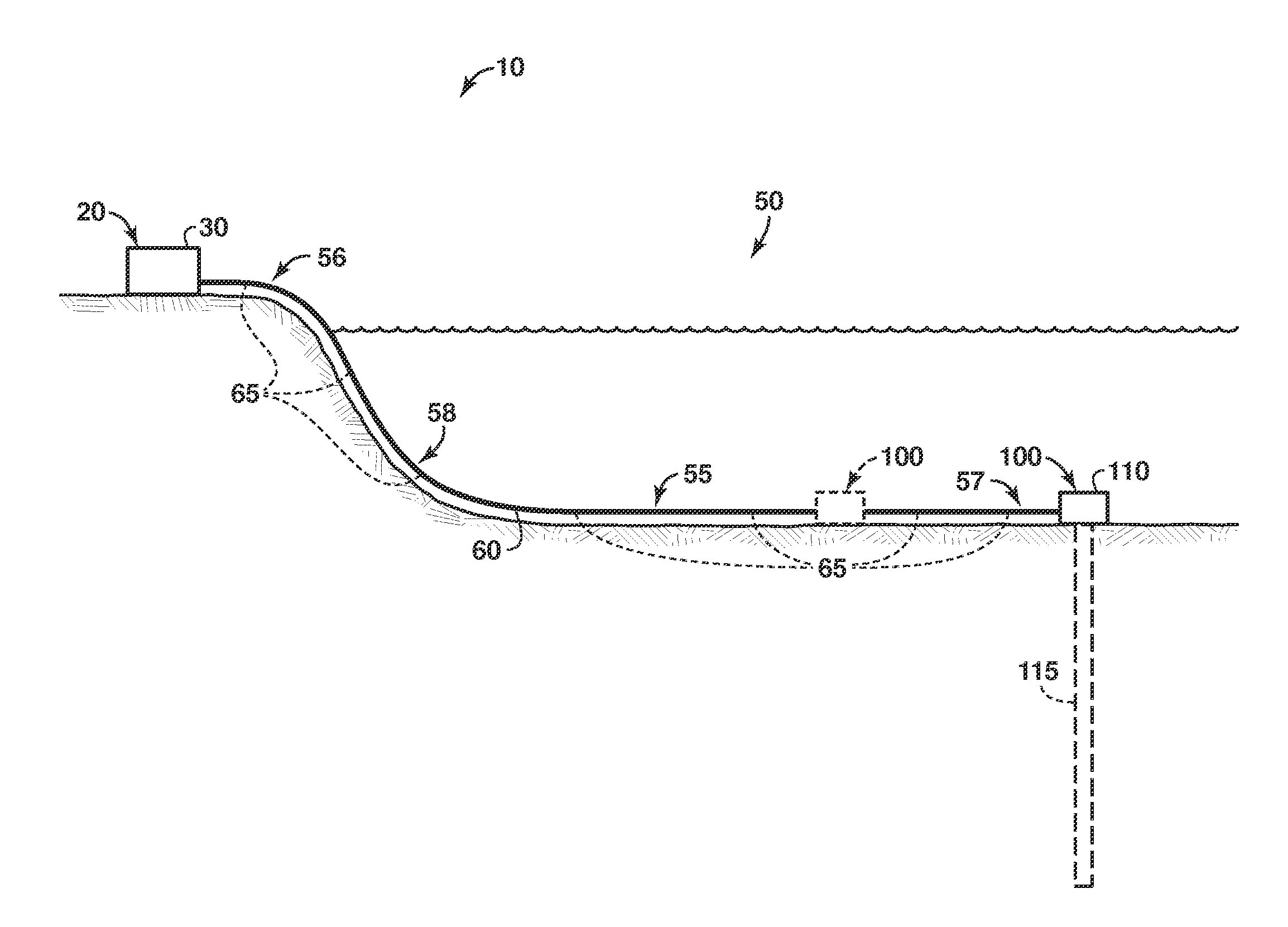
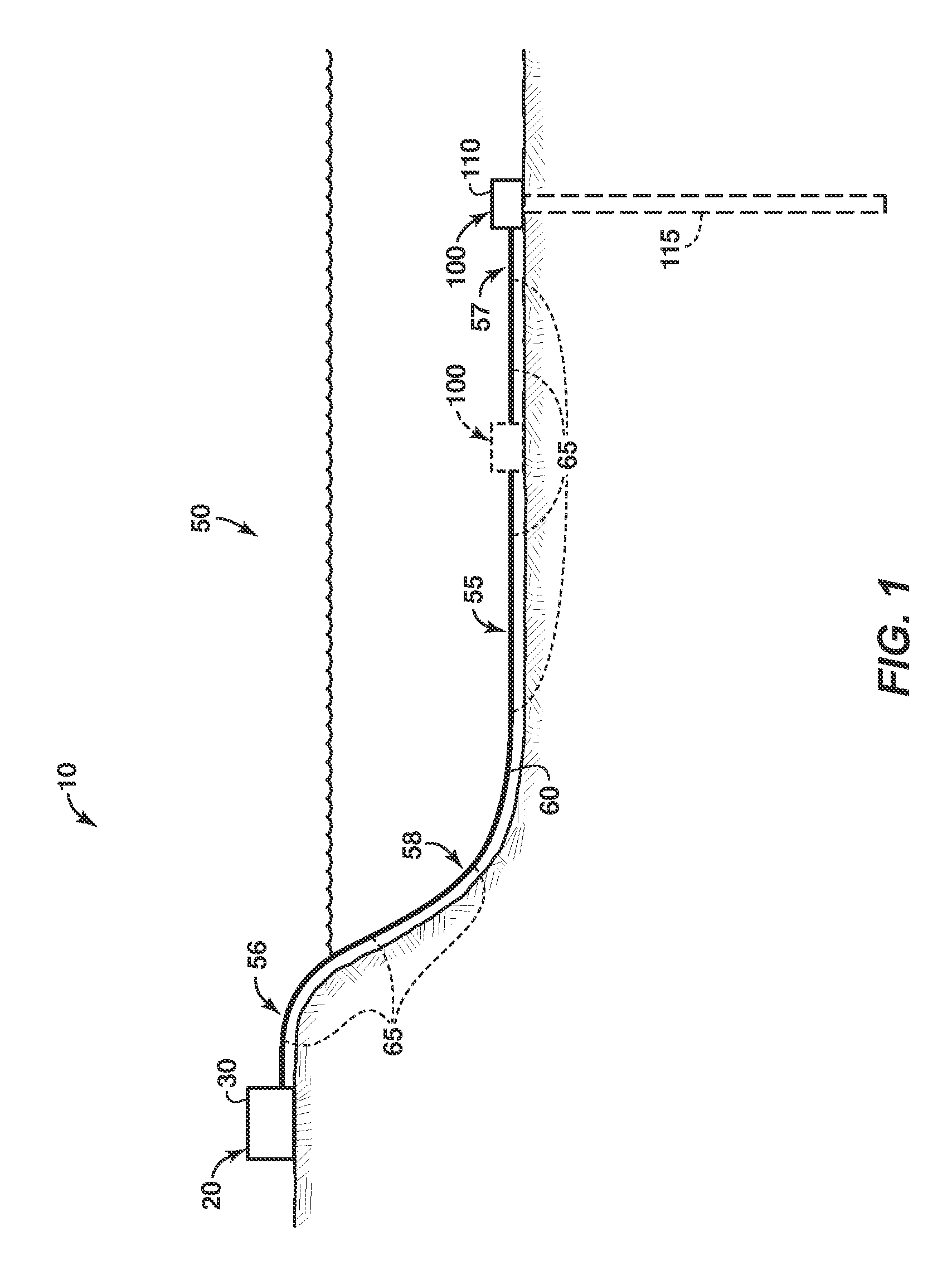
[0019]FIG. 1 provides a schematic representation of an illustrative, non-exclusive example of a power generating and distributing assembly 10 according to the present disclosure. Power generating and distributing assembly 10 includes any suitable electricity source 20, such as power generation system 30, as well as subsea power distribution system 50. Subsea power distribution system 50 provides electrical energy from electricity source 20 to one or more subsea energy consuming devices 100, such as subsea hydrocarbon recovery equipment 110.

[0020]Electricity source 20 may include any suitable source of electrical energy, or electrical potential, including sources of high voltage alternating current (HVAC). Illustrative, non-exclusive examples of sources of electrical energy according to the present disclosure include any suitable type and number of electrical utility grid, energy storage device, battery, capacitor, inductor, and / or power generation system 30. Power generation system ...


PUM

PropertyMeasurementUnit
lengthaaaaaaaaaa
lengthaaaaaaaaaa
lengthaaaaaaaaaa

Abstract

Systems and methods for impedance compensation in a subsea power distribution system. These systems and methods include the use of a plurality of distributed impedance compensation devices to control the impedance of the subsea power distribution system. These systems and methods may include the use of distributed impedance compensation devices that are inductively coupled to a subsea power transmission cable associated with the subsea power distribution system. These systems and methods also may include the use of distributed impedance compensation devices that are inductively powered by the subsea power transmission cable. These systems and methods further may include the use of distributed impedance compensation devices that are marinised for use under water.

Description

CROSS-REFERENCE TO RELATED APPLICATIONS[0001]This application claims the benefit of U.S. provisional patent application No. 61 / 514,346 filed on Aug. 2, 2011 entitled SYSTEMS AND METHODS FOR DISTRIBUTED IMPEDANCE COMPENSATION IN SUBSEA POWER DISTRIBUTION, the entirety of which is incorporated herein.FIELD OF THE DISCLOSURE[0002]The present disclosure is directed to systems and methods for controlling the impedance of a subsea power distribution system, and more particularly to systems and methods that utilize a plurality of distributed impedance compensation devices to control the impedance of a subsea power distribution system.BACKGROUND OF THE DISCLOSURE[0003]As the oil and gas industry discovers and develops deeper and more remote subsea hydrocarbon reserves, subsea tiebacks that may supply recovered hydrocarbons to production facilities economically and over longer distances become increasingly important. These long-distance subsea tiebacks may utilize subsea pressure boosting eq...

Claims


Application Information

Patent Timeline
Patent Type & Authority Applications(United States)
IPC IPC(8): H02J3/00G05B6/02H01B9/00
CPCH02J3/22
Inventor MCJUNKIN, SAMUEL T.WHEAT, JOHN S.
Owner MCJUNKIN SAMUEL T
Learn More