
Medical handpiece with automatic power switching means

a handpiece and automatic technology, applied in the field of medical instruments, can solve the problems of limiting the power input to tissue, affecting the operation efficiency of the operation, and reducing so as to reduce the trauma to the tissue and facilitate the control of the power transmission to the operative tip

Inactive Publication Date: 2010-08-17
MISONIX INC
View PDF42 Cites 22 Cited by
  • Summary
  • Abstract
  • Description
  • Claims
  • Application Information

AI Technical Summary

Benefits of technology

The present invention is a medical instrument and method for performing surgical operations that automatically delivers power to the operative tip only when the instrument is being moved in a preselected direction relative to the patient. This is achieved through a motion sensor that detects the motion of the instrument and a switching device that is operatively connected to the instrument and the motion sensor. The instrument is designed to minimize trauma to the patient's tissues and can be used in ultrasonically assisted liposuction. The technical effects of the invention include improved precision and efficiency in surgical procedures and reduced trauma to the patient.

Problems solved by technology

By simply moving his hand, he is able to apply power to the surgical site and remove the tip of the probe even when the power is on, limiting the power input to tissue.
However, in applications such as liposuction, the surgeon would have a difficult time in controlling power requirements.
Therefore, this energy can be considered waste and it actually goes into tissue heating.
If the temperature rises above the necrosis point, burning, scarring and other deleterious effects will arise.
It would be difficult and tiring for the surgeon to time the on and off controls with his hand movements, since they are rapid and repetitive.
In fact, the power is even reduced on the push stroke, when it is most needed increasing the effort needed to advance the cannula through the body.

Method used


Image

  • Medical handpiece with automatic power switching means
  • Medical handpiece with automatic power switching means
  • Medical handpiece with automatic power switching means

Examples


Embodiment Construction

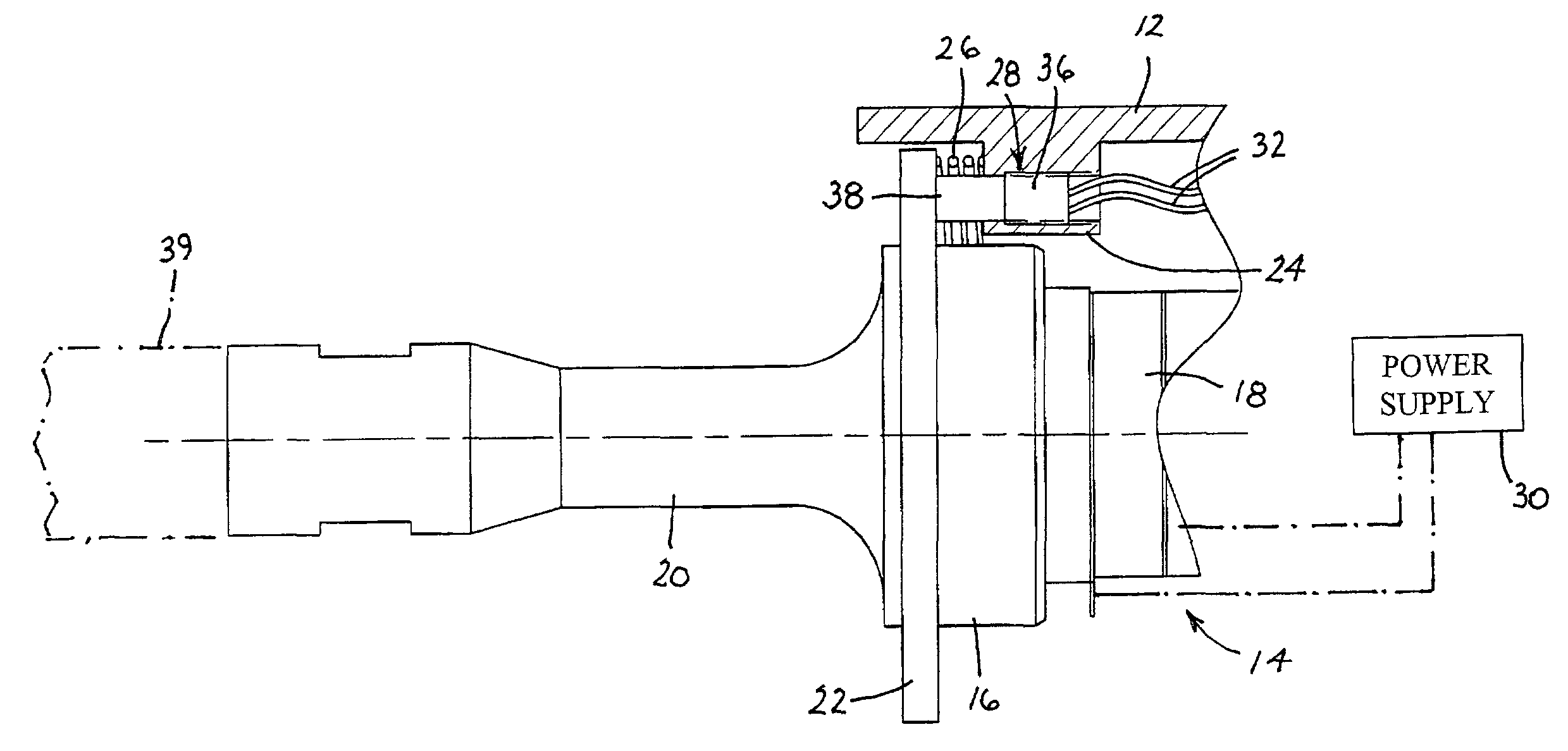
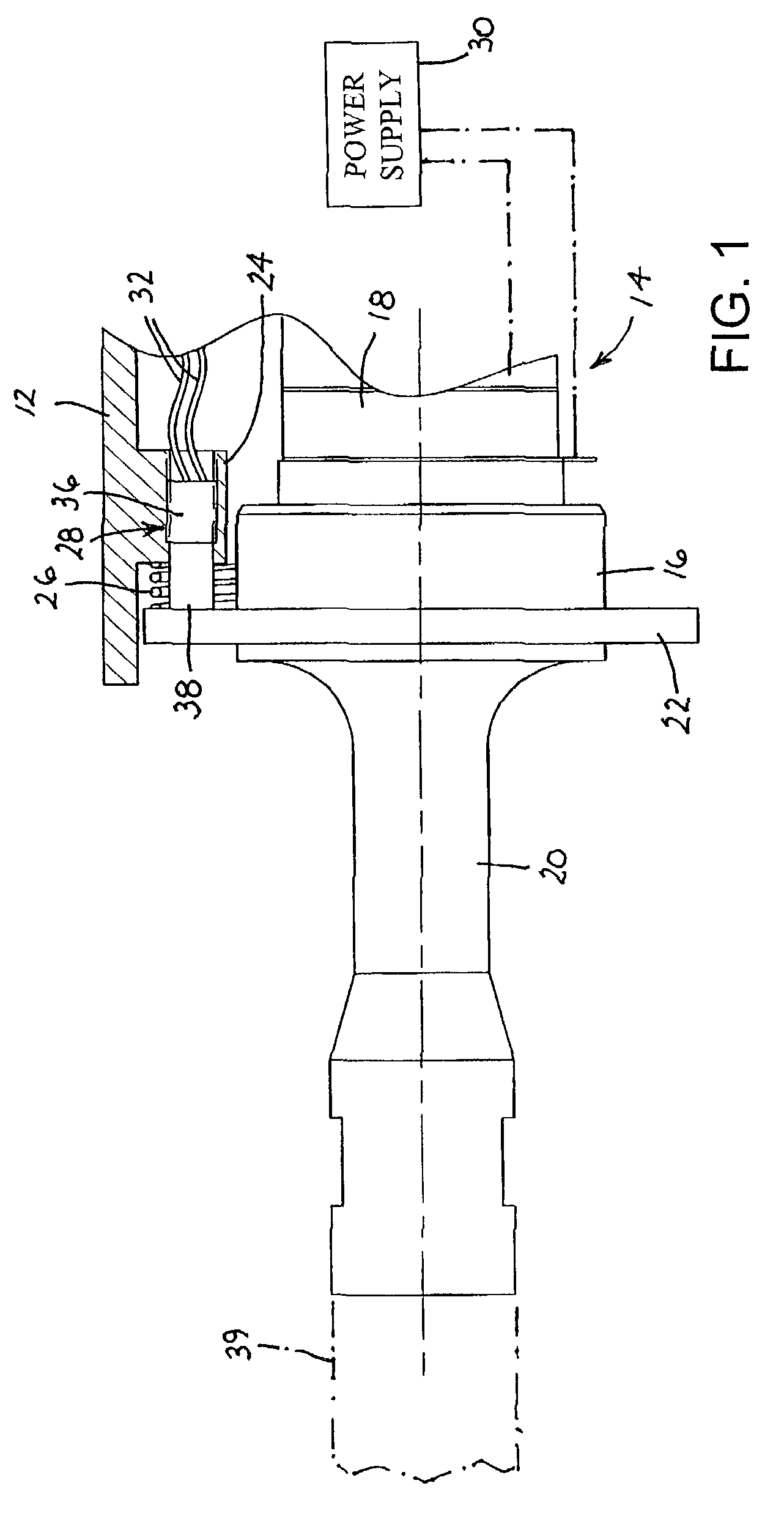
[0039]Together with improvements disclosed herein, the drawings show sections of a medial instrument handpiece disclosed in U.S. Pat. No. 5,769,211, the disclosure of which is hereby incorporated by reference.

[0040]As illustrated in FIG. 1, an ultrasonic handpiece comprises a handgrip portion in the form of a sleeve 12 that surrounds and is movably mounted to a transducer array 14. Transducer array 14 includes a front driver 16 and a stack of piezoelectric crystals 18. Front driver 16 is coupled to an ultrasonic horn 20 that amplifies ultrasonic pressure waves produced by the stack of crystals 18. Front driver 16 is provided at a vibration node with an outwardly extending circumferential flange 22, while sleeve 12 is provided with an inwardly extending circumferential flange (or a plurality of angularly spaced inwardly extending projections) 24. A helical compression spring 26 surrounds front driver 16 and is sandwiched between flanges 22 and 24. Compression spring 26 biases flanges...


PUM


Abstract

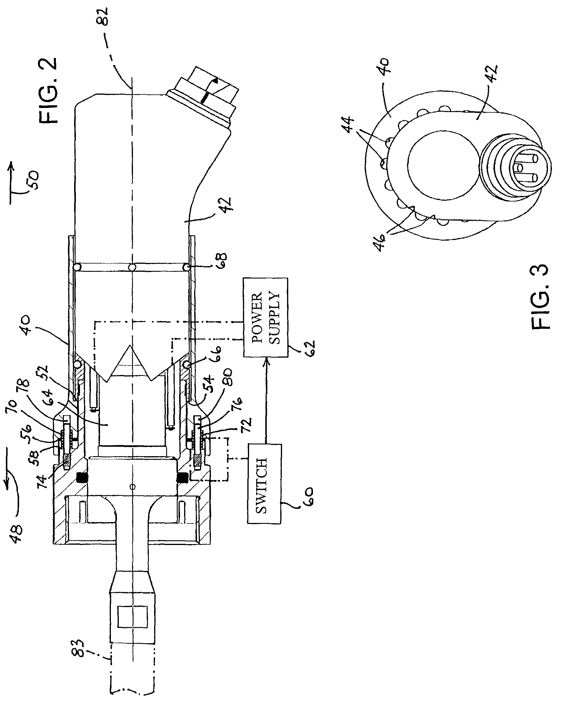
A medical instrument includes a handpiece, an electromechanical transducer disposed in the handpiece, and an electrical circuit disposed at least partially in the handpiece for supplying alternating electrical current of a predetermined frequency to the transducer. A probe is operatively connected to the transducer for transmitting vibrations generated by the transducer to an operative site in a patient. A switching device is mounted to the handpiece and is operatively connected to the circuit and the transducer for enabling the supply of power to the transducer during a motion of the probe in a preselected direction relative to the handpiece and for disabling the supply of power to the transducer upon a termination of motion of the probe in the preselected direction.

Description

BACKGROUND OF THE INVENTION[0001]This invention relates to a medical instrument and to an associated method. More particularly, this invention relates to a medical instrument and method wherein power to an operative tip is automatically controlled.[0002]Ultrasonic devices have been used to remove soft and hard tissue from mammalian bodies for over three decades, at least. These devices and methods for their use have been well documented in the art, such as U.S. Pat. No. 4,223,676 to Wuchinich, U.S. Pat. No. 4,827,911 to Broadwin and U.S. Pat. No. 5,419,761 to Narayanan et al. Applications include phacoemulsification, ablation of tumors in the liver and spine and subcutaneous removal of adipose tissue, also known as ultrasonic liposuction.[0003]Most of the instruments used for these applications have several elements in common. These are an electrical generator which transforms line or battery power to relatively high voltage RF frequencies in the 20 kc to 100 kc range, a transducer ...

Claims


Application Information

Patent Timeline
Patent Type & Authority Patents(United States)
IPC IPC(8): A61B18/14A61B17/00A61B17/32A61B19/00
CPCA61B17/320068A61B18/1445A61B17/1622A61B2017/00367A61B2017/0042A61B2019/465A61M2202/08H01H9/06A61B2090/065A61B2017/320069A61B2017/32007A61B2017/320089
Inventor MANNA, RONALD R.ISOLA, SCOTTNOVAK, THEODORE A. D.
Owner MISONIX INC
Learn More