
System and Method for Packaging of High-Voltage Semiconductor Devices

Inactive Publication Date: 2013-01-24
US SEC THE ARMY THE
View PDF0 Cites 10 Cited by
  • Summary
  • Abstract
  • Description
  • Claims
  • Application Information

AI Technical Summary

Benefits of technology

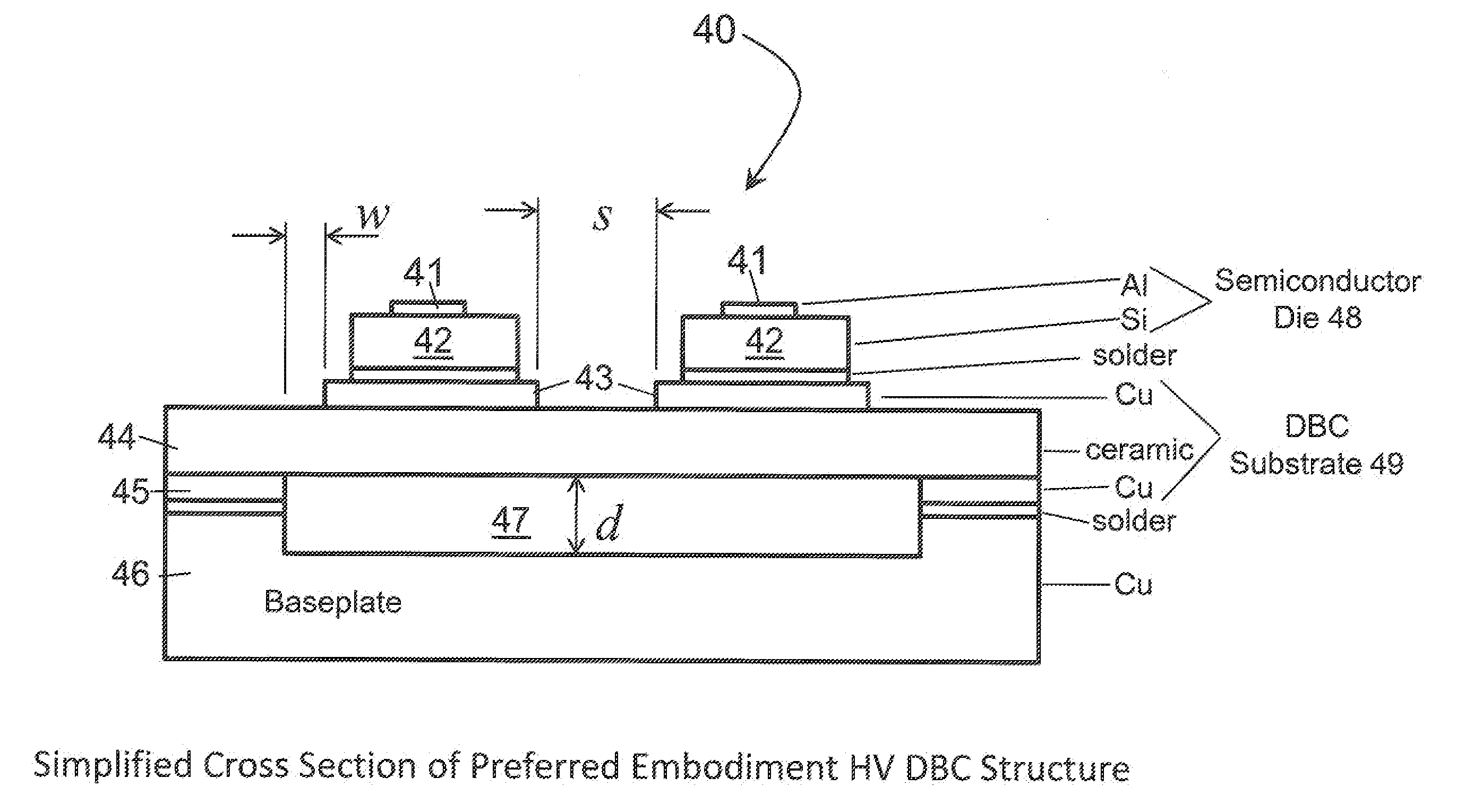
The invention provides a method for reducing electrical stresses on semiconductor dies by creating a dielectric region underneath them on the substrate. This improves the die's ability to withstand voltage breakdown and reduce the risk of material failure. Additionally, the thickness of the substrate and dielectric region are critical parameters in the design for optimal results. The invention also provides a method for making an electronic device structure by either removing a portion of the substrate to create a dielectric region or producing the substrate with a dielectric region. This results in a higher distance between the base plate and the substrate, reducing the capacitive effect and further improving the device's performance.

Problems solved by technology

This leads-to a design trade-off between overall package size and component reliability.
Because DBC ceramic is generally only available up to thicknesses of 1 mm, the reduction of electric field required to quench partial discharge degradation usually not possible using only DBC.

Method used


Image

  • System and Method for Packaging of High-Voltage Semiconductor Devices
  • System and Method for Packaging of High-Voltage Semiconductor Devices
  • System and Method for Packaging of High-Voltage Semiconductor Devices

Examples


Embodiment Construction

[0042]The present invention now will be described more fully hereinafter with reference to the accompanying drawings, in which embodiments of the invention are shown. However, this invention should not be construed as limited to the embodiments set forth herein. Rather, these embodiments are provided so that this disclosure will be thorough and complete, and will fully convey the scope of the invention to those skilled in the art. In the drawings, the thickness of layers and regions may be exaggerated for clarity. Like numbers refer to like elements throughout. As used herein the term “and / or” includes any and all combinations of one or more of the associated listed items.

[0043]The terminology used herein is for the purpose of describing particular embodiments only and is not intended to limit the full scope of the invention. As used herein, the singular forms “a”, “an” and “the” are intended to include the plural forms as well, unless the context clearly indicates otherwise. It wil...


PUM


Abstract

A method and an electronic device structure comprising at least one access lead to adapted to be connected to an electrical circuit; at least one substrate region; at least one semiconductor die positioned on the substrate; the at least one semiconductor die being operatively connected to the at least one access lead; a dielectric region extending below the at least one semiconductor die; the dielectric region being formed by creating a cavity in the at least one substrate region; whereby the dielectric region operates to reduce electric field stresses produced by the at least one semiconductor die to thereby reduce the possibility of material failure and voltage breakdown. The method of making an electronic device structure comprises providing at least one substrate region; providing at least one semiconductor die located on the at least one substrate region; removing a portion of the at least one substrate region to provide a dielectric region within the substrate extending below the at least one semiconductor die; whereby the dielectric region within the at least one substrate region operates to reduce electric field stresses produced by the at least one semiconductor die to thereby reduce the possibility of material failure and voltage breakdown.

Description

GOVERNMENT INTEREST[0001]The invention described herein may be manufactured, used, and / or licensed by or for the United States Government.BACKGROUND OF THE INVENTION[0002]Driving factors in modern, high-voltage DC-DC power conversion include size and efficiency. While the maturation of resonant converter circuits and supporting component technologies has decreased the volume of the converters' front-end, the process of inverting high-frequency, high-voltage on the output has not changed significantly over several decades. Designers continue to weigh the trade-off between diode recovery time and reverse breakdown voltage required by silicon devices as discussed further in J. Wang, et al., “Characterization, Modeling of 10-kV SiC JBS Diodes and Their Application Prospect,” IEEE Energy Conversion Congress and Exposition (ECCE), pp. 1488-1493 (2009). From a system perspective, one can use high-speed, lower-voltage diodes and a transformer with many secondary windings; lower-speed, high-...

Claims


Application Information

Patent Timeline
IPC IPC(8): H01L29/06H01L21/02
CPCH01L29/872H01L29/1608H01L2924/1305H01L2924/12032H01L2924/13055H01L2224/49111H01L2224/48472H01L25/072H01L23/62H01L23/3735H01L2224/48091H01L2924/00014H01L2924/00H01L2224/73265
Inventor TIPTON, CHARLES W.IBITAYO, OLADIMEJI O.
Owner US SEC THE ARMY THE
Learn More