
Method For Simulating Fractional Multi-Phase/Multi-Component Flow Through Porous Media

a multi-phase/multi-component fluid flow and fractional technology, applied in the direction of instruments, cad techniques, analogue processes for specific applications, etc., can solve the problems of equipment malfunction, leakage problems and/or equipment malfunction, and other materials may not have effective contact with solid materials, etc., to achieve improved evaluations and estimates.

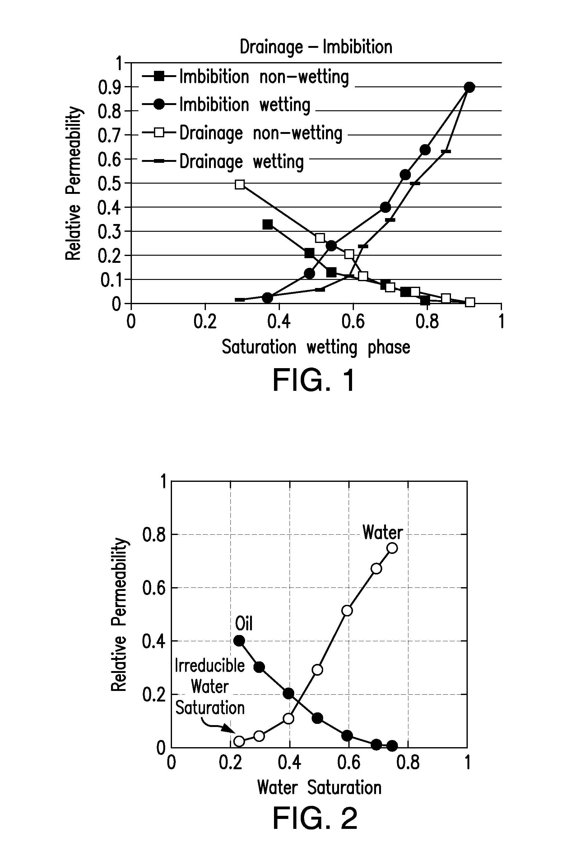
Active Publication Date: 2013-01-17
HALLIBURTON ENERGY SERVICES INC
View PDF3 Cites 57 Cited by
  • Summary
  • Abstract
  • Description
  • Claims
  • Application Information

AI Technical Summary

Benefits of technology

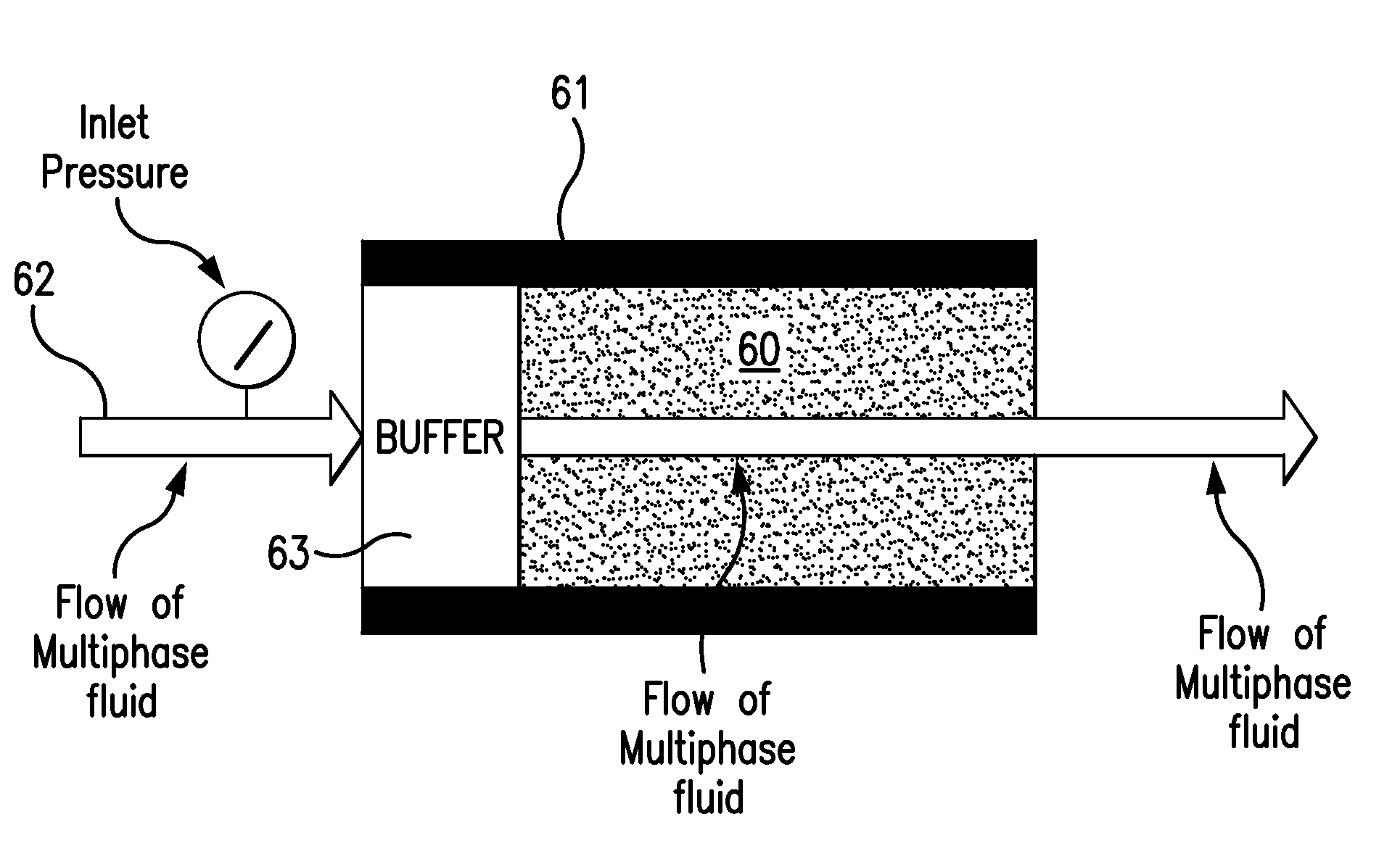
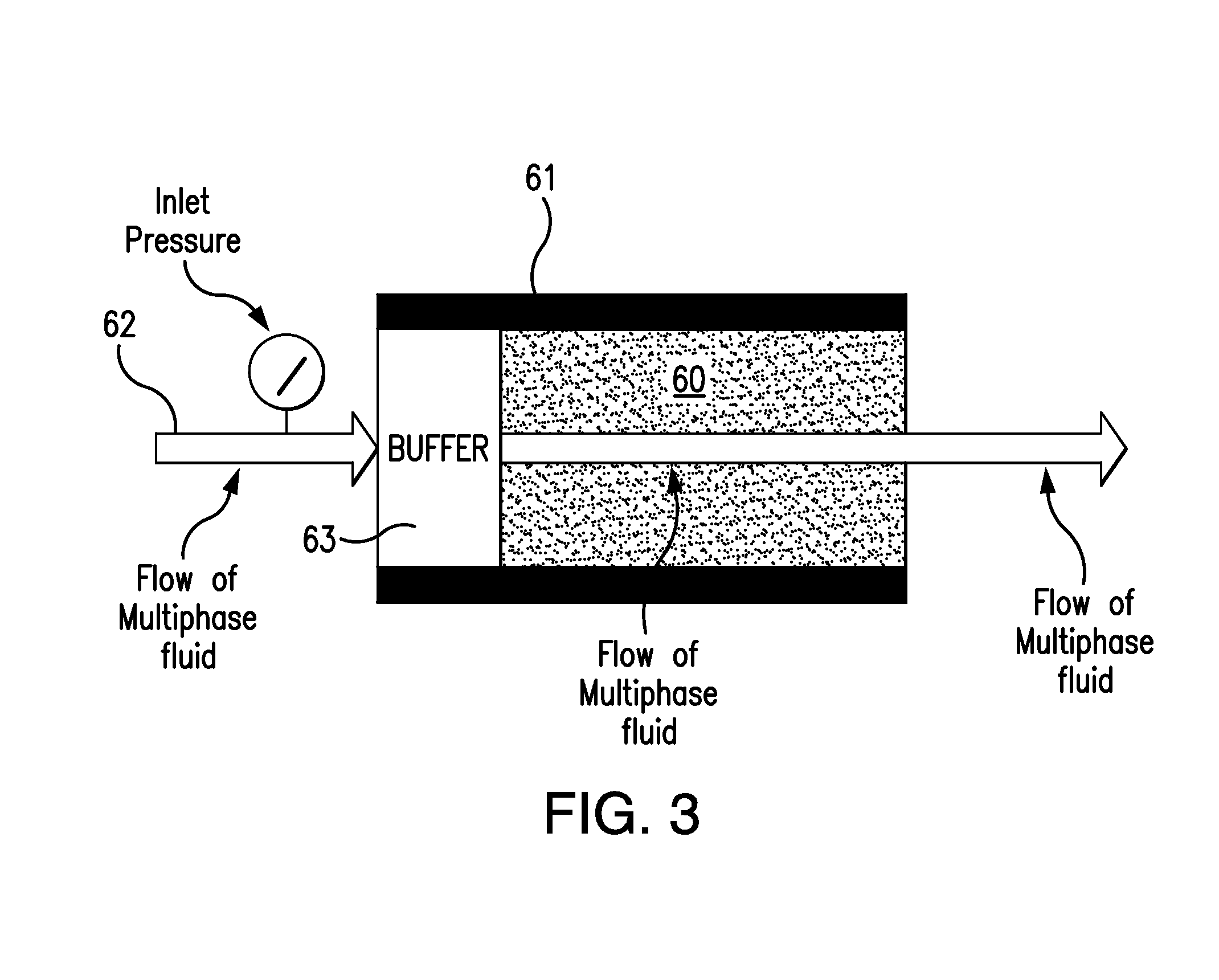
The present invention provides a method for setting boundary conditions for numerical methods, such as computational fluid dynamics (CFD) simulations, that more accurately represent real-world conditions and improve calculation speed and stability. Additionally, the invention provides a method to calculate or estimate multiphase, multi-component fluid flow through porous media, such as oil reservoirs, by using the indicated method and / or system. The calculated or estimated relative permeabilities can be used to provide improved evaluations and estimates of the productivity of a subterranean reservoir, and the methods and systems can also be used for other types of porous media.

Problems solved by technology

For example, one fluid may strongly adhere to the surfaces within a given pore while another material may have no effective contact with the solid material.
Creating artificial conditions to replicate downhole conditions is difficult, expensive, and / or imprecise.2. The pressures required to achieve desired flow rates may be extremely high causing leakage problems and / or equipment malfunctions.3. A large volume of fluid must be processed for the sample to come close to steady state.4. Tests can take a very long time up to weeks or months or more than a year to complete.5. Very tight formations such as shales may be difficult or impossible to measure.6. Initial conditions such as saturation, wettability, and fluid distributions are difficult to establish.7. Establishing wettability in the lab is difficult because cores are usually cleaned prior to the testing and initial wettability cannot be accurately restored.8. In the lab, it is difficult and expensive to conduct tests with reservoir fluids at reservoir conditions.
Mixing gas and oil at reservoir temperatures and pressures is difficult and can be dangerous.
The choice between solid or pore may not always be clear due to differences in the resolution of the scan and the minimum size of the grains in the porous medium.
Boundary conditions are a quite complex problem in numerical methods.
Difficulties can arise from the fact that the pressure and distribution of the phases and velocities at the inlet of the digital simulation are unknown and these conditions must be established such that they mimic the physical conditions.
In the case of relative permeability in oil and gas formations, hydrocarbons at high temperatures and pressures, often above the critical point, are difficult to control and dangerous to handle.
Numerical methods also may suffer some drawbacks, including one or more of the following:1. Initial and boundary conditions are difficult or impossible to assess which results in inability in some cases to accurately calculate relative permeabilities or instability in computation.
This is especially true when fractional flow of one or more components is small.2. The distribution of wettability in space and time within a porous medium is difficult to assess.

Method used


Image

  • Method For Simulating Fractional Multi-Phase/Multi-Component Flow Through Porous Media
  • Method For Simulating Fractional Multi-Phase/Multi-Component Flow Through Porous Media
  • Method For Simulating Fractional Multi-Phase/Multi-Component Flow Through Porous Media

Examples


example 1

[0201]A sample of a carbonate rock was selected for analysis using a representative method of the present invention. The sample plug was weighed (125.299 g), physically measured for its diameter and length, and photographed. The plug was marked for orientation and placed in oven to dry and weighed again (124.447 g).

[0202]The plug was imaged on a MicroXCT-200 manufactured by Xradia at a resolution of 0.5×, at approximately 40 microns (pm) per voxel. The plug was scanned with the Ceretom Dual Energy X-Ray CT Scanner manufactured by Neurologica to determine bulk density and atomic number. A sub-sampling location was selected that showed typical atomic number. Areas with high atomic number were avoided.

[0203]A laser was used to mill out a 4 mm diameter pillar from the carbonate sample (see the square region indicated in FIG. 10). The square region in FIG. 10 is the area of the carbonate sample selected for further analysis. The selected sub-sample was imaged on the MicroXCT-200 scanner ...


PUM


Abstract

A method for computing or estimating fractional, multi-phase / multi-component flow through a porous medium employing a 3D digital representation of a porous medium and a computational fluid dynamics method to calculate flow rates, pressures, saturations, internal velocity vectors and other flow parameters is described. The method employs a unique method of introducing non-wetting and wetting fluids into the pores at the inlet face of the 3D digital representation of a porous medium and a novel process control application to achieve quasi-steady state flow at low inlet concentrations of non-wetting fluid. In addition, the method of the present invention reduces the time required to simulate to complete the fluid dynamic calculations. The resulting values of flow of non-wetting fluid, wetting fluid, saturation, and other parameters are used to generate plots of relative permeability imbibition and drainage curves. Computerized systems and programs for performing the method are also provided.

Description

[0001]This application claims the benefit under 35 U.S.C. §119(e) of prior U.S. Provisional Patent Application No. 61 / 506,680, filed Jul. 12, 2011, which is incorporated in its entirety by reference herein.BACKGROUND OF THE INVENTION[0002]The present invention relates to a method to estimate multi-phase / multi-component fluid flow through porous media and to estimate relative permeabilities at various levels of saturation. Relative permeability data estimated with the present method can be used, for example, in many areas such as oil field simulation, estimating oil or gas production rates, estimating recoverable reserves, designing hydrocarbon recovery strategies such as fracturing or “fracking”, life sciences, paper manufacturing, food industry, agriculture, and other areas relating to geology and geophysics. The present invention also relates to a computerized system and components thereof for performing such a method.[0003]Relative permeability is used to quantify multiphase flow...

Claims


Application Information

Patent Timeline
IPC IPC(8): G06G7/57G01N15/08
CPCG06F2217/16G06F17/5009G06F2111/10G06F30/20G01N33/241G01V20/00
Inventor PRISCO, GIUSEPPE DETOELKE, JONASMU, YAOMING
Owner HALLIBURTON ENERGY SERVICES INC
Learn More