
Apparatus and method for distributing a string of secret bits over a quantum channel

Inactive Publication Date: 2013-01-17
UNIVERSITY OF GENEVA
View PDF2 Cites 32 Cited by
  • Summary
  • Abstract
  • Description
  • Claims
  • Application Information

AI Technical Summary

Benefits of technology

The patent describes a quantum cryptography communication system and method for securely distributing a sequence of symbols between an emitter and a receiver. The system has several advantages, including its simplicity and robustness, its security against photon-number splitting attacks, and its independence of witness states and reduced classical communication expenses. The method involves measuring the coherence between quantum systems using an interferometer, and detecting any eavesdropper by monitoring the phase coherence between quantum systems. The technical effects of the patent include increased secure key rates at longer distances and an extended reach of the secret key distribution, as well as better statistics and increased secure key rate (finite key analysis).

Problems solved by technology

Unfortunately both of these cryptographic schemes consume key material and render it unfit for use.
The problem with this approach is that the security of the key depends on the fact that it has been protected during its entire lifetime, from its generation to its use, until it is finally discarded.
In addition, it is unpractical and very tedious.
Unfortunately, all such mathematical methods for key agreement rest upon unproven assumptions, such as the difficulty of factoring large integers.
Their security is, thus, only conditional and questionable.
Future mathematical developments may prove them totally insecure.
This implies that a spy eavesdropping on the quantum channel cannot get information on the key without introducing errors in the key exchanged between the emitter and the receiver.
For a given qubit, it is, thus, not possible for an eavesdropper to determine its quantum state with absolute certainty.
In practice, one has to use imperfect apparatuses, which implies that some errors are present in the bit sequence, even without interaction of the eavesdropper with the qubits.
It is not possible for the receiver to distinguish between them deterministically.
This attack is particularly powerful in real apparatuses, where the receiver expects to detect only a small fraction of the qubits sent by the emitter, because of quantum channel attenuation and limited detector efficiency.
When considering a large number of qubits, this non-zero probability produces a measurable error rate.
In spite of the fact that polarization states of the electromagnetic field represent natural candidates for the implementation of QC, they are difficult to use in practice when optical fibers carry the qubits.
While the original QC proposal called for the use of single photons as qubits to encode the key, their generation is difficult and good single-photon sources do not exist yet.
The PNS attack is particularly powerful in the real world, where the receiver expects to detect only a small fraction of the photons, because of quantum channel attenuation and limited detector efficiency.
An eavesdropper trying to measure bit values sometimes obtains inconclusive results.
In this protocol, PNS attacks on individual weak coherent states are obviously useless as the bit value is coded in the phase difference between adjacent states.
This would however destroy the phase coherence with the other neighboring states and introduce errors with a non-zero probability.

Method used


Image

  • Apparatus and method for distributing a string of secret bits over a quantum channel
  • Apparatus and method for distributing a string of secret bits over a quantum channel
  • Apparatus and method for distributing a string of secret bits over a quantum channel

Examples


Embodiment Construction

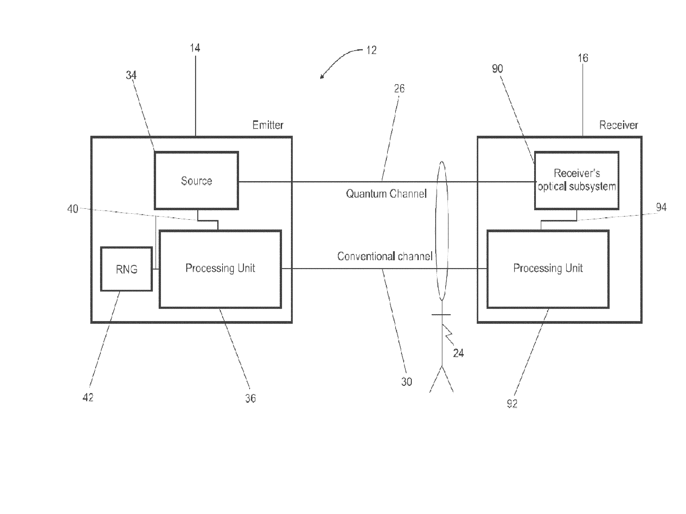
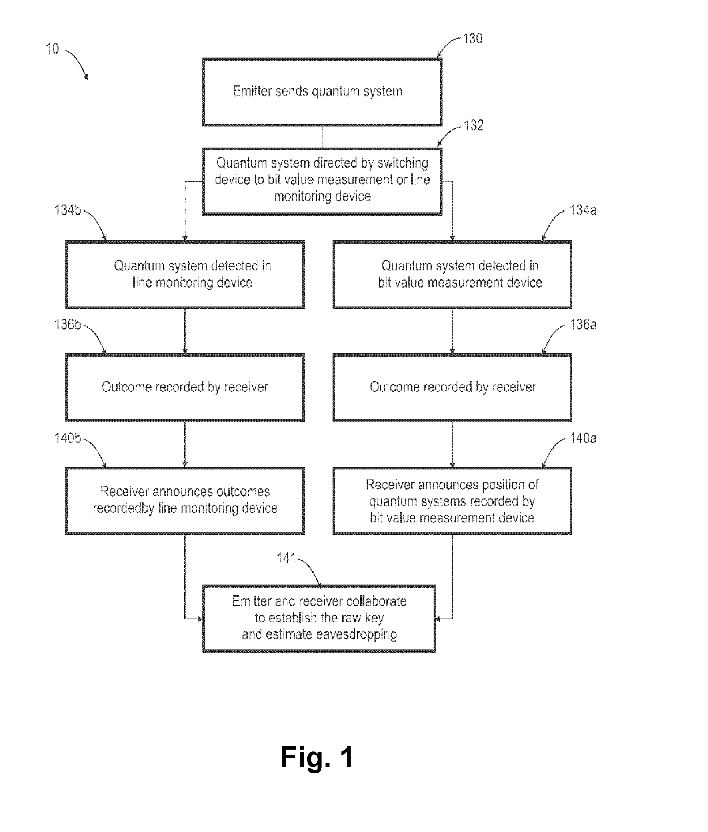
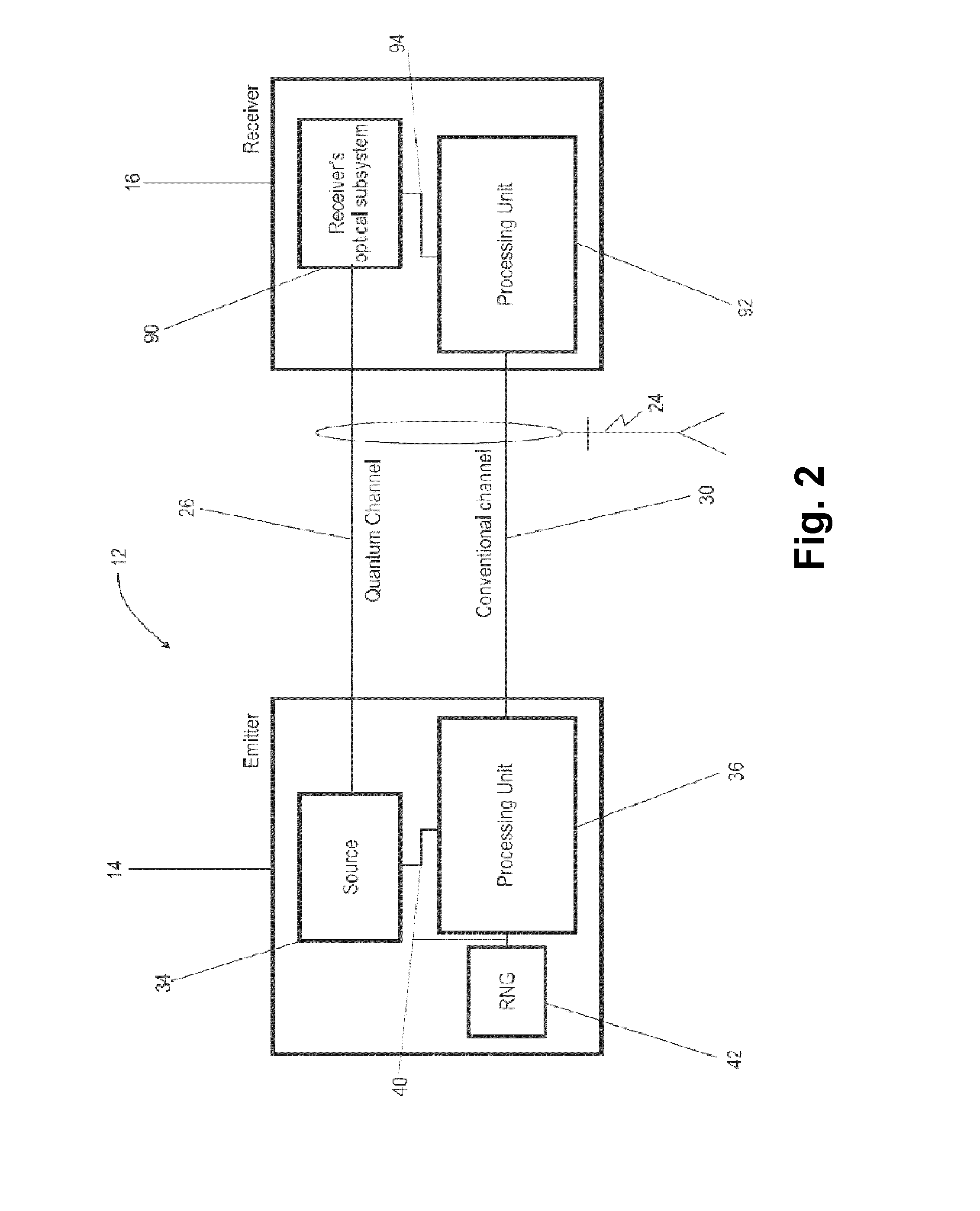
[0046]In FIG. 2, reference numeral 12 refers to a quantum cryptography communication system or apparatus for exchanging between an emitter station 14 and a receiver station 16 a sequence of symbols via a quantum channel 26, according to the method 10 illustrated in FIG. 1.

[0047]As illustrated in FIG. 3, the sequence of symbols are coded on a stream 22 of quantum systems 20, constituted by pairs of time-ordered coherent states, used to transmit the raw key (e.g. a data string such as 101100101001111001001010 . . . 01010100) and allowing the emitter station 14 and the receiver station 16 to estimate the maximum amount of information an eavesdropper 24 can have obtained on the raw key. This raw key can subsequently be distilled into a secure key (e.g. a distilled data string such as 10011000 . . . 1100 of fewer digits than the raw data string) through an appropriate key distillation procedure, known in the art.

[0048]As shown in FIG. 2, the emitter station 14 and the receiver station 16...


PUM


Abstract

For distributing a sequence of symbols, an emitter station transmits to a receiver station quantum systems through a quantum channel. Each of the quantum systems belongs to a set of at least two non-orthogonal quantum states and comprises a group of at least two weak coherent states of an electromagnetic field. Each weak coherent state is in a time bin of duration t. Centers of neighboring weak coherent states in a group are separated by a time T1, with T1 greater than t. Centers of neighboring weak coherent states in adjacent quantum systems are separated by a time T2, with T2 greater than t. In addition, any two weak coherent states separated by T1+T2 are phase coherent. The receiver station comprises an optical subsystem configured to check, for received quantum systems, phase coherence of two weak coherent states of time bins separated by T1+T2.

Description

FIELD OF THE INVENTION[0001]The present invention relates generally to the field of quantum cryptography, and more particularly to an apparatus and a method enabling two users to exchange a sequence of symbols via a quantum channel. Specifically, the present invention relates to a system and a method for distributing a sequence of secret bits between an emitter station and a receiver station connected by a quantum channel and assessing the maximum amount of information an eavesdropper could have obtained on the sequence.BACKGROUND OF THE INVENTION[0002]If two users possess shared random secret information (below the “key”), they can achieve, with provable security, two of the goals of cryptography: 1) making their messages unintelligible to an eavesdropper and 2) distinguishing legitimate messages from forged or altered ones. A one-time pad cryptographic algorithm achieves the first goal, while Wegman-Carter authentication achieves the second one. Unfortunately both of these cryptog...

Claims


Application Information

Patent Timeline
IPC IPC(8): H04K1/00
CPCH04L9/0852H04B10/70
Inventor ZBINDEN, HUGOWALENTA, NINOLIM, CHARLES CI WEN
Owner UNIVERSITY OF GENEVA
Learn More