
Instrument for positioning a cup component of an orthopaedic joint prosthesis

a technology for orthopaedic joints and instruments, applied in the field of instruments for positioning the cup component of orthopaedic joints, can solve problems such as affecting the bearing properties of orthopaedic joints

Inactive Publication Date: 2012-12-13
DUPUY INT LTD
View PDF4 Cites 0 Cited by
  • Summary
  • Abstract
  • Description
  • Claims
  • Application Information

AI Technical Summary

Benefits of technology

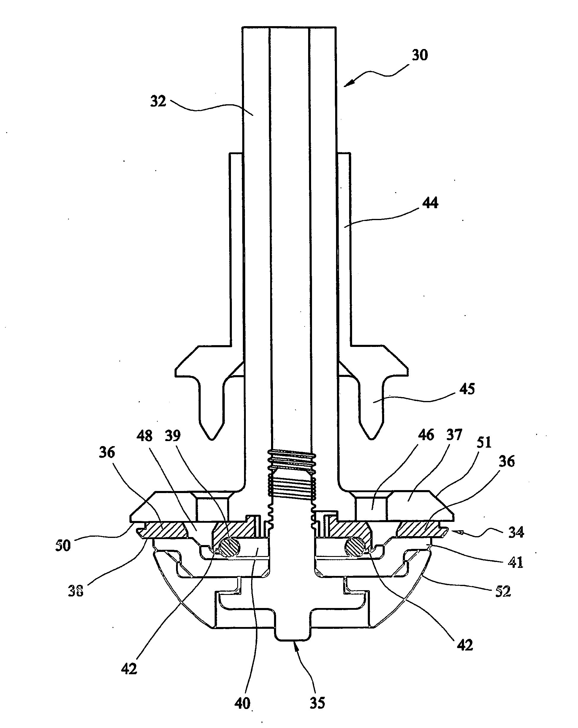
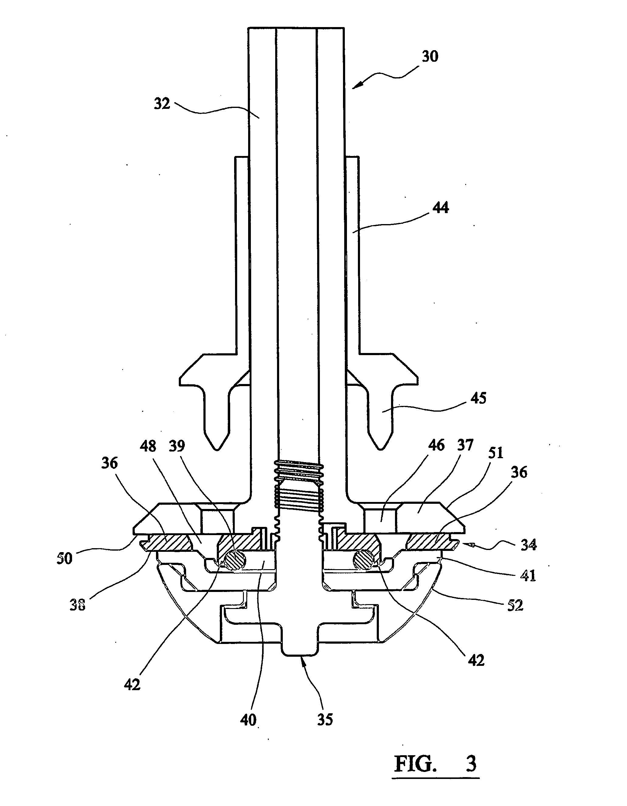
[0010]Preferably, the support comprises at least one support plate which the retractable flange portion slides against. Preferably, the support presents a pair of opposite support surfaces and the retractable flange portion slides between them. It is particularly preferred that the support presents a support surface which the side of the retractable flange portion facing towards the end of the instrument can slide against. This can help to support the flange against forces which tend to separate the prosthesis component from the instrument.
[0039]The thickness of the wall of the cup component will depend on factors such as its application, the material from which it is made, and the overall construction of the joint prosthesis. It will generally be preferred for the wall thickness (not including any coatings or other layers which are applied for fixation) to be as thin as possible to minimise the amount of bone which has to be resected from around the component, consistent with ensuring sufficient strength of the component, and ability to withstand wear due to articulation during use. When the component is made from a hard material such as a metal, a ceramic or a ceramic coated metal, and has a smooth internal bearing surface, its wall thickness will generally be at least about 1.5 mm, preferably at least about 2.0 mm, more preferably at least about 3.0 mm. When the component is made from a polymeric material (such as ultrahigh molecular weight polyethylene), its wall thickness might be at least about 2.5 mm, preferably at least about 3.0 mm, more preferably at least about 3.5 mm. The wall thickness of the component can vary between the polar and other regions. For example, the wall thickness can be greatest at the pole, and least at or close to the open mouth. For example, in the case of a component formed from a hard material, the wall thickness can be about 4 to 6 mm at the pole, and 3 to 4 mm at or close to the open mouth.

Problems solved by technology

Scratching or otherwise damaging that surface can impair the bearing properties of the prosthesis.

Method used


Image

  • Instrument for positioning a cup component of an orthopaedic joint prosthesis
  • Instrument for positioning a cup component of an orthopaedic joint prosthesis
  • Instrument for positioning a cup component of an orthopaedic joint prosthesis

Examples


Embodiment Construction

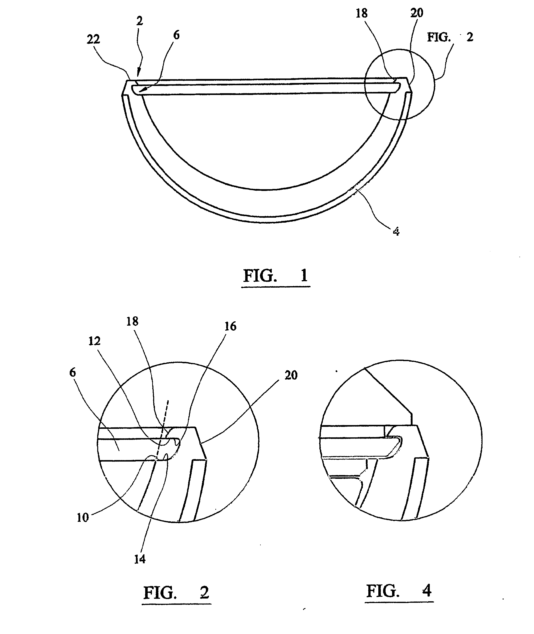
[0047]Referring to the drawings, FIG. 1 shows an acetabular cup 2 which has a generally hemispherical shape. It is formed from a cobalt-chromium based alloy. The external surface of the cup has a porous layer 4 formed on it, which is provided by particles which are sintered so that they bond to one another and to the surface. The use of this technique to create a porous surface is known, and is used in connection with products sold by DePuy Orthopaedics Inc under the trade mark POROCOAT. Such a porous surface promotes fixation of the implant as a result of ingrowth of bone tissue.

[0048]A groove 6 is formed in the internal surface of the cup close to the open mouth 8. The groove is defined by an inner lip 10, an outer lip 12, and by opposite walls 14, 16 which are parallel at the open edge of the groove. Preferably, the walls of the groove are approximately perpendicular to the axis of polar the cup component.

[0049]The internal surface of the cup within the region defined by the inne...


PUM

PropertyMeasurementUnit
Forceaaaaaaaaaa
Metallic bondaaaaaaaaaa

Abstract

An instrument for positioning a cup component of an orthopaedic joint prosthesis includes a shaft, a housing attached to the distal end of the shaft, at least two flange portions carried on the shaft on which the cup component can be fixed, and a unitary spring element disposed about the shaft axis and disposed between the at least two flange portions and the axis of the shaft. The housing includes a base plate and extends from the shaft transversely relative to the shaft axis. The at least two flange portions can move relative to the base plate in a direction transverse to the shaft axis between an in-use position, where at least a portion of each of the at least two flange portions contacts the inner surface of the cup component, and a retracted position where the at least a portion of each of the at least two flange portions is moved towards the shaft axis so as to allow the cup component to be released from the instrument. The spring element biases each of the at least two flange portions towards the in-use position.

Description

CROSS REFERENCE TO RELATED APPLICATION[0001]The present application is a continuation of Ser. No. 10 / 587,733 filed Feb. 3, 2004.BACKGROUND OF THE INVENTION[0002]This invention relates to an instrument for positioning a cup component of an orthopaedic joint prosthesis.[0003]Certain orthopaedic joint prostheses include a hollow cup with an inner surface which defines a generally hemispherical hollow region, and another component which has a spherical part which can be received in the hollow region for articulation relative to the cup component. Such joint prostheses can include hip joint prostheses and shoulder joint prostheses. The exterior of the cup will contact the prepared surface of the patient's bone in which the component is to be implanted. The interior of the cup will present a smooth bearing surface to the spherical part of the other component of the joint prosthesis. The bearing surface can be provided by a single piece cup component. Alternatively, the cup component can c...

Claims


Application Information

Patent Timeline
IPC IPC(8): A61B17/56A61F2/00A61F2/30A61F2/34A61F2/40A61F2/46
CPCA61F2/0095A61F2310/00592A61F2/34A61F2/4081A61F2/4609A61F2/4612A61F2002/30324A61F2002/30579A61F2002/30606A61F2002/30718A61F2002/30822A61F2002/30968A61F2002/345A61F2002/4631A61F2250/0036A61F2310/00017A61F2310/00023A61F2310/00029A61F2310/00179A61F2/30767
Inventor FENTON, GARYALFONSI, STEFANOMOORE, GARYFLETT, MAGNUS
Owner DUPUY INT LTD
Learn More