
Surgical Implant

a surgical and implant technology, applied in the field of surgical implants, can solve the problems of poorly osseointegrative, difficult to achieve the effect of osseointegration, and incompatibility of the surface of polymers such as paek family polymers, and implants made of these materials

Active Publication Date: 2012-12-06
DEPUY SYNTHES PROD INC
View PDF11 Cites 17 Cited by
  • Summary
  • Abstract
  • Description
  • Claims
  • Application Information

AI Technical Summary

Benefits of technology

[0025]In some embodiments of the method for producing the polymeric surgical implant, such as a polyaryletherketone (PAEK) surgical implant, the valve metal layer is applied by a process independently selected from the group consisting of: cathodic arc deposition, magnetron sputtering physical vapor deposition, pulsed laser deposition, electron beam physical vapor deposition, high power impulse magnetron spu...

Problems solved by technology

PEEK is, however, known to be poorly osseointegrative and therefore there is a need to overcome this disadvantage.
The surface of polymers, such as polymers in the PAEK family, is often not compatible with soft or hard tissues like bones.
Implants made of these materials may poorly integrate and finally dysfunction.
However, these techniques (such as VPS) may not ensure a good anchoring, between the titanium oxide surface and tissue, and the high process temperature may contribute to the deterioration of the properties of the polymer.
In addition, application of a thick VPS coating on complex geometries may be challenging due to the shadowing effect of the spray and the relative large thickness (e.g. 200 μm) that may leverage out any fine structure of the implant surface would have.
Furthermore the so-called “splash” structure of plasma spray coatings may not exhibit a suitable pore structure as the pores are fine and elongated and the overall porosity limited.
Additionally, titanium layers made by physical vapor deposition (“PVD”) may be dense and thin, for example approximately 1 micrometer or less, and thus, in some circumstances, titanium PVD thin layers may not be satisfactory for implants.

Method used


Image

  • Surgical Implant
  • Surgical Implant
  • Surgical Implant

Examples


Embodiment Construction

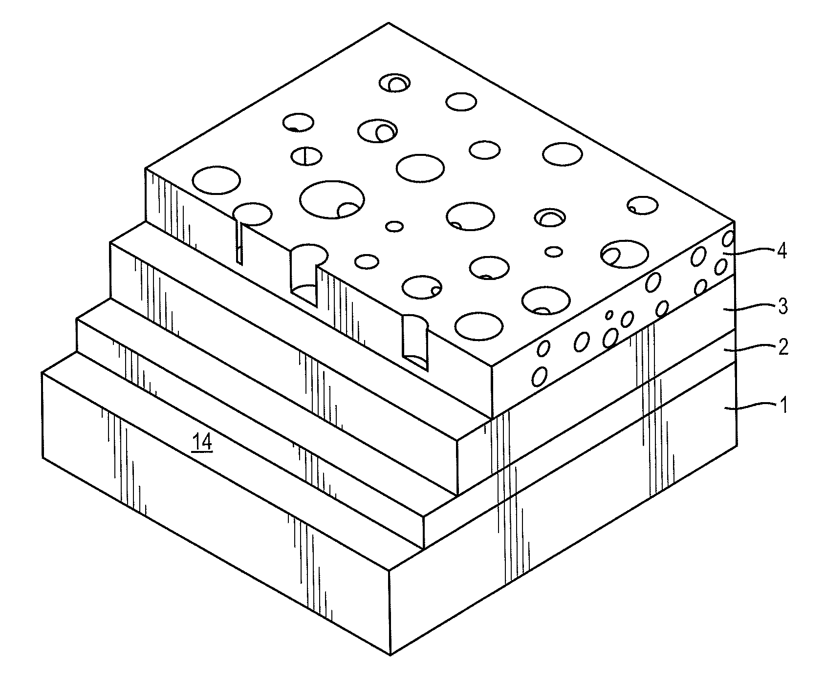
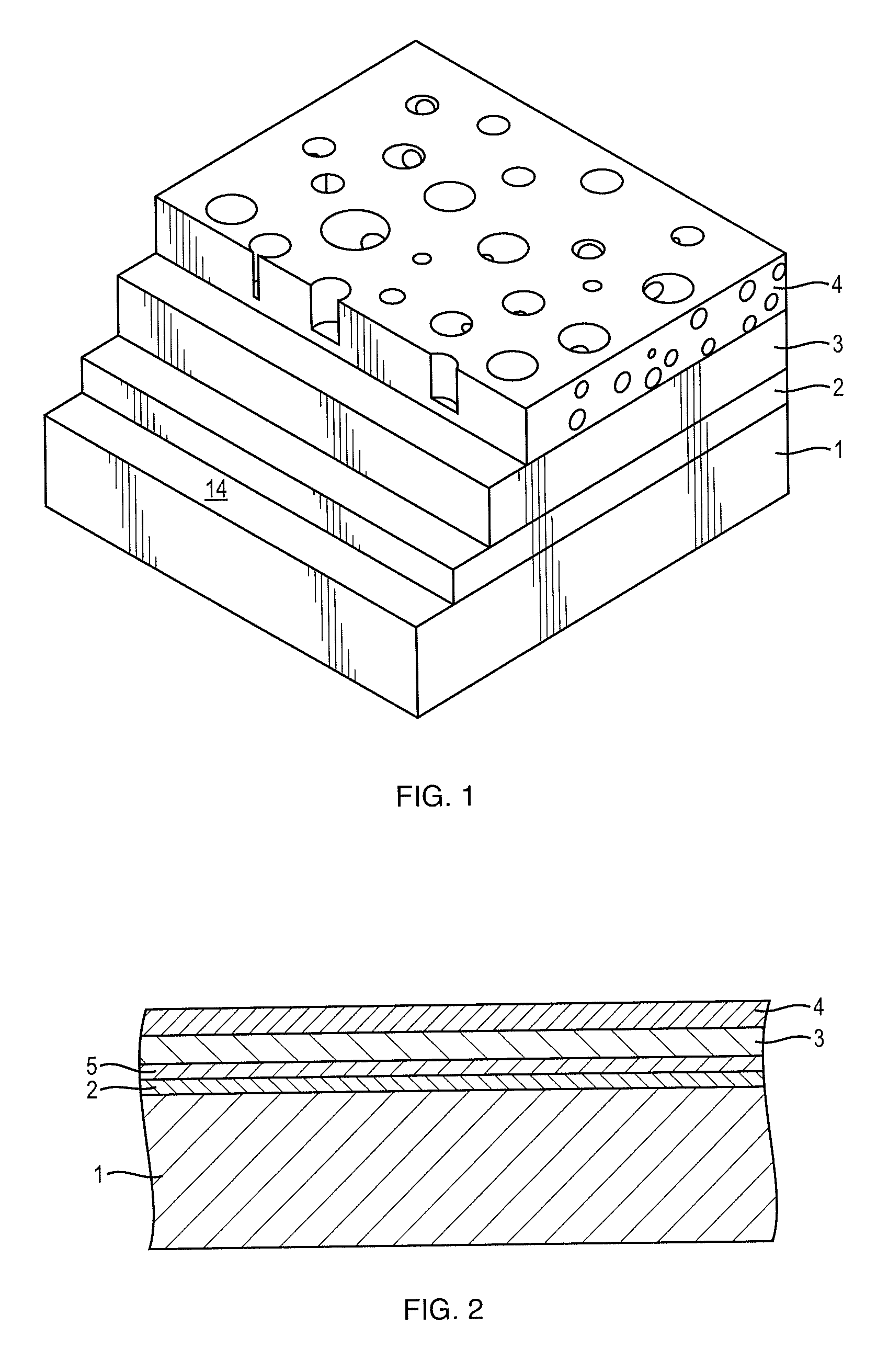
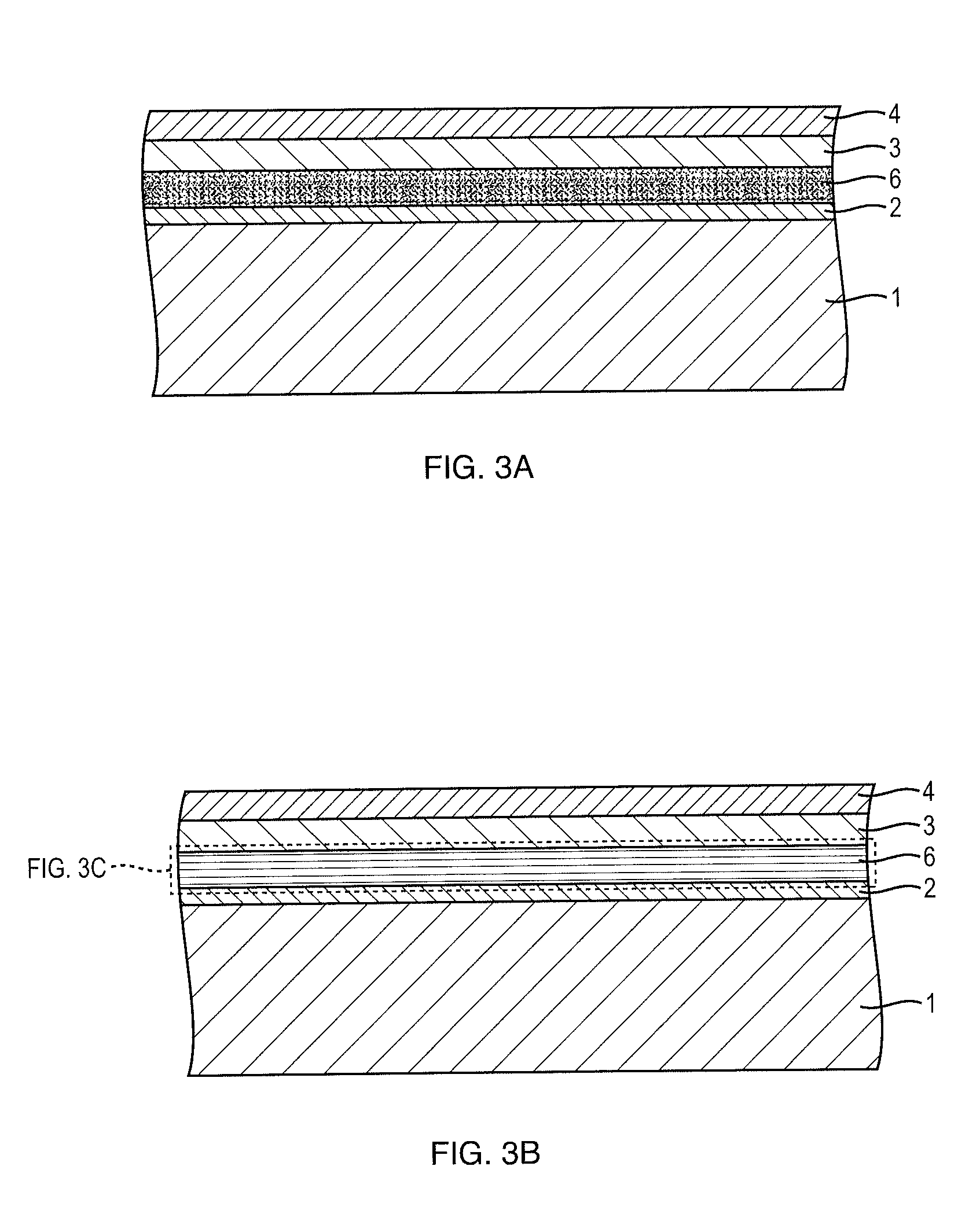
[0038]Reference will now be made in detail to the various embodiments of the present disclosure, examples of which are illustrated in the accompanying drawings FIGS. 1-6. Wherever possible, the same reference numbers will be used throughout the drawings to refer to the same or like parts.

[0039]In an aspect, the present invention provides a surgical implant comprising a substrate having an exterior surface and a plurality of layers disposed over the substrate exterior surface. The substrate comprises a polymeric material, and wherein the plurality of layers comprises: (i) an activated substrate surface layer; (ii) a valve metal layer; and (iii) a porous valve metal oxide layer, wherein the valve metal layer is disposed between the activated substrate layer and the porous valve metal oxide layer.

[0040]Typically, an exemplary substrate for use in the surgical implant in accordance with the present invention comprises a polymeric material. The polymeric material may be a thermoplastic p...


PUM

PropertyMeasurementUnit
Lengthaaaaaaaaaa
Lengthaaaaaaaaaa
Lengthaaaaaaaaaa

Abstract

A surgical implant comprising: a substrate having an exterior surface and a plurality of layers disposed over the substrate exterior surface. The substrate comprises a polymeric material, and the plurality of layers comprises: an activated substrate surface layer; a valve metal layer; and a porous valve metal oxide layer, wherein the valve metal layer is disposed between the activated substrate layer and the porous valve metal oxide layer. The disclosure provides for a method for producing a polymeric surgical implant. The exterior substrate surface is treated by one or more processes comprising: plasma activation; electron beam irradiation; ultraviolet light; and low energy Ar+ ion beam irradiation; producing an activated substrate surface layer. A plurality of layers is applied over the activated substrate surface layer. The surface is converted by a spark-anodization process in an alkaline bath containing Ca and P ions into a layer of porous valve metal oxide.

Description

CROSS-REFERENCE TO RELATED APPLICATIONS[0001]The present application claims priority to U.S. Provisional Patent Application No. 61 / 492,985, filed Jun. 3, 2011, the disclosure of which is incorporated by reference herein in its entirety.FIELD OF THE INVENTION[0002]This invention relates to surgical implants based on polymeric material with multiple layered coatings resulting in improved compatibility with soft and hard tissue.BACKGROUND OF THE INVENTION[0003]Bone anchors made of polymeric materials such as polyether ether ketone (“PEEK”) are interesting as they are fully compatible with standard imaging techniques like X-Rays, computed tomography (“CT”) or Magnetic Resonance Imaging (“MRI”). In particular no artifact is generated when using CT or MRI that would disturb diagnostics. In case of X-rays, PEEK anchors are not visible. PEEK is, however, known to be poorly osseointegrative and therefore there is a need to overcome this disadvantage.[0004]The surface of polymers, such as pol...

Claims


Application Information

Patent Timeline
IPC IPC(8): A61F2/02
CPCA61L27/306C23C28/42A61L27/18A61L27/34A61L31/06A61L31/088A61L31/10A61L31/146A61L31/18A61L2300/44A61L2420/02A61L2420/04A61L2420/08A61L2430/02A61L2430/20A61L27/56C23C28/345C23C28/34C23C28/322C23C28/321C08L83/04C08L71/10C08L71/00C23C14/08
Inventor VOISARD, CYRILGEDET, PHILIPPEBOUDUBAN, NICOLAS
Owner DEPUY SYNTHES PROD INC
Learn More