
Catalysts for use in electrochemical applications and electrodes and devices using same

Active Publication Date: 2012-11-22
THE OHIO STATES UNIV
View PDF10 Cites 9 Cited by
  • Summary
  • Abstract
  • Description
  • Claims
  • Application Information

AI Technical Summary

Benefits of technology

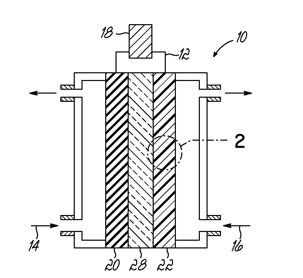
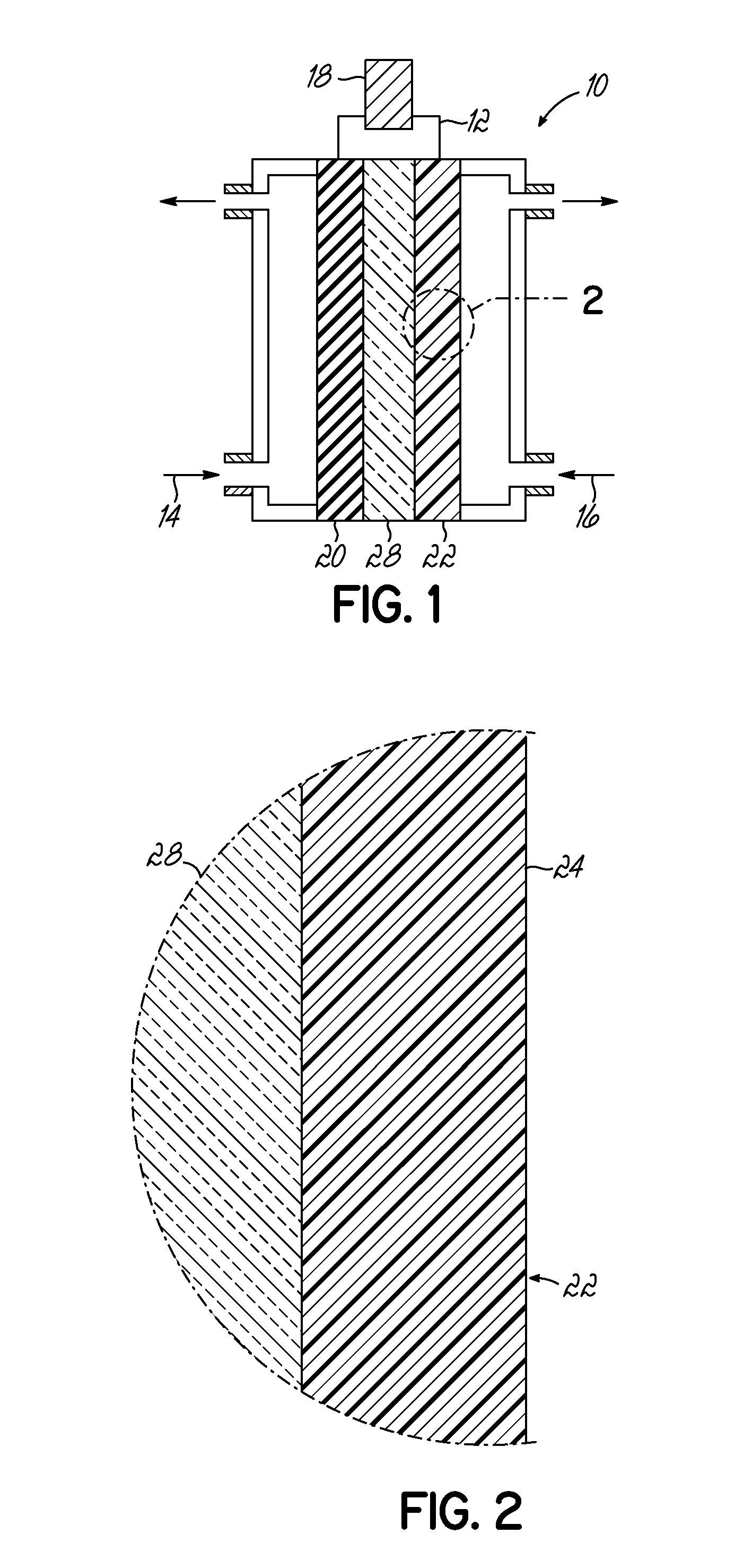
[0009]To these and other ends, in one embodiment, an electrode for reduction of an oxidant comprises a phosphorus-doped carbon-containing catalyst represented by the chemical formula CNxPy, where x is from 0 to about 10 wt. % and y is from about 1 ppm to about 10 wt. %. The phosphorus-doped carbon-containing c

Problems solved by technology

These processes are thermochemical in nature and often result in unburned fuel, particulates, and other noxious chemicals being injected into the atmosphere.
In the absence of downstream environmental controls, such as, scrubbers, coal burning power plants can introduce undesirable gases, residual pollutants, and particulates into the air.
Similarly, if not for downstream environmental controls, unburned fuel and incomplete combustion products often pollute the air.
Fuel cells, such as the PEM fuel cell, are, however, not without their operational difficulties.
For example, the Oxygen Reduction Reaction (ORR) at the cathode of a PEM fuel cell is often slow and is generally the largest source of inefficiency in a PEM fuel cell.
The slow kinetics associated with the ORR are thought to be due to the oxygen-oxygen pi-bond being relatively strong and thus difficult to break.
On the other hand, however, inclusion of platinum increases the capital costs associated with PEM fuel cells and thus, from a cost perspective, inhibits large scale introduction of these devices.

Method used


Image

  • Catalysts for use in electrochemical applications and electrodes and devices using same
  • Catalysts for use in electrochemical applications and electrodes and devices using same
  • Catalysts for use in electrochemical applications and electrodes and devices using same

Examples


examples

[0052]CNxPy catalysts and CNx catalysts were synthesized by pyrolyzing acetonitrile over growth medium of a seed material of MgO impregnated with 2 wt. % Fe via incipient-wetness-impregnation (IWI). Each of the growth mediums for the CNxPy and CNx were different. For the CNxPy catalysts, the Fe—MgO seed material was subject to an additional IWI step with tri-phenylphosphine (TPP) and diethyl ether at predetermined ratios of P to Fe as indicated in FIGS. 4 and 5. As shown, the CNxPy catalysts were grown with P / Fe ratios of 0.33, 1, 3, 20, and 30. This additional treatment was conducted prior to pyrolyzing acetonitrile over the seed material.

[0053]To isolate the effect of the additional IWI step with TPP, a second impregnation of diethyl ether without TPP was prepared (labeled “P / Fe=blank” or phosphorus free) from which a CNx catalyst was grown. The resulting CNx (P / Fe=0 blank) catalyst was also measured for comparison and is shown in FIGS. 4 and 5. In addition, another CNx catalyst (...


PUM

PropertyMeasurementUnit
Fractionaaaaaaaaaa
Structureaaaaaaaaaa

Abstract

An electrode for reduction of an oxidant including a phosphorus-doped carbon-containing catalyst represented by the chemical formula CNxPy, where x is from 0 to about 10 wt. % and y is from about 1 ppm to about 10 wt. %. A device for producing electricity by facilitating an electrochemical reaction between a fuel and an oxidant. The device including a first electrode for oxidizing the fuel to produce protons and electrons. The device further includes a second electrode in electrical communication with the first electrode when electrically connected to the external circuit. The second electrode includes a phosphorus-doped carbon-containing catalyst for reducing the oxidant and is represented by the chemical formula CNxPy, where x is from 0 to about 10 wt. % and y is from about 1 ppm to about 10 wt. %. The device further includes an electrolyte, such as, a membrane, separating the first electrode from the second electrode.

Description

CROSS REFERENCE TO RELATED CASES[0001]This application claims priority to U.S. Provisional Patent Application Ser. No. 61 / 487,431 filed May 18, 2011, the disclosure of which is incorporated by reference herein in its entirety.STATEMENT REGARDING FEDERALLY SPONSORED RESEARCH OR DEVELOPMENT[0002]Embodiments of the invention disclosed in this application may have been developed with the use of research grant / contract funds under Basic Energy Sciences Contract No. GE-FG02-07ER15896, sponsored by the U.S. Department of Energy.TECHNICAL FIELD[0003]The present invention relates generally to catalysts, and more specifically to catalysts for use in electrochemical reactions.BACKGROUND[0004]The global demand for power continues to increase. Often, the combustion or burning of fossil fuels produces power to meet this demand. These processes are thermochemical in nature and often result in unburned fuel, particulates, and other noxious chemicals being injected into the atmosphere. For example, ...

Claims


Application Information

Patent Timeline
IPC IPC(8): B01J31/26H01M8/10C07F9/50H01M2/00H01M4/90B82Y30/00
CPCH01M4/96B82Y30/00Y02E60/50H01M2008/1095
Inventor OZKAN, UMIT S.DEAK, DIETER VONBIDDINGER, ELIZABETH
Owner THE OHIO STATES UNIV
Learn More