
Lighting device with light source and wavelength converting element

Inactive Publication Date: 2012-10-18
KONINKLIJKE PHILIPS ELECTRONICS NV +1
View PDF4 Cites 29 Cited by
  • Summary
  • Abstract
  • Description
  • Claims
  • Application Information

AI Technical Summary

Benefits of technology

[0004]It is an object of the invention to mitigate or at least diminish the above-mentioned problem and / or other problems. The invention particularly aims at providing a cheap lighting device having a light source and an efficient wavelength converting element with phosphors with a metal-ion activator which is excitable via a partially forbidden absorption. Especially the scattering losses in the converting element should be relatively low. Another object of the invention is providing an efficient wavelength converting element of the indicated type suitable for use in a lighting device as well as the manufacture of such wavelength converting element.
[0012]In still another embodiment of the invented lighting device, the polymer is a fluorine-containing polymer. Polymers of this type can be used with great advantage when compounded with phosphors having a metal-ion activator which is excitable via a partially forbidden electronic transition. Especially phosphors comprising a Mn(IV)-activated fluoride compound, such as compounds of the type K2SiF6:Mn(IV) and Na3Li3Al2F12:Mn(IV), can be applied with great advantage in wavelength converting elements of lighting devices. The refractive index of these phosphors and polymers match rather well. Wavelength converting elements comprising a phosphor as described before, being compounded with an organic polymer as described before appear to be quite transparent and therefore show unexpected low scattering.
[0014]In a still further embodiment of the lighting device according to the present invention, the amount of phosphor in the polymer ranges from 10-20 vol. %. Experiments have shown that a phosphor amount smaller than 10 vol. % causes that the conversion elements should be designed rather thick (>2 mm) in order to obtain a sufficient conversion efficiency. Phosphor amounts in the polymer larger than 20 vol. % results in converting elements having a thickness lower than 0.1 mm, which elements are difficult to handle in practice. Optimal amounts of the phosphor in the polymer range from 13-17 vol. %. Using these amounts, converting elements can be manufactured having an optimal combination of thickness and absorption efficiency.
[0016]The invention relates also to a wavelength converting element, which is suitable for use in a lighting device. More particularly, such element according to the invention comprises a phosphor with a metal-ion activator which is excitable via a partially forbidden electronic transition, said phosphor being compounded with a polymer, the phosphor and the polymer being chosen such that the difference in their refractive index is smaller than 0.1. Said phosphor comprises preferably a Mn(IV)-activated fluoride compound, more preferably a compound comprising at least one of K2SiF6:Mn(IV) and Na3Li3Al2F12:Mn(IV). The phosphor may also comprise a coating to increase the stability of the phosphor. Preferably the coating material consists substantially of a fluoride with very low solubility in water, such as calcium fluoride. Said polymer can be an inorganic polymer, but an organic polymer is preferred. Fluorine-containing polymers appear to be very useful, especially co-polymers comprising at least two of tetrafluoroethylene, hexafluoropropylene and vinylidene fluoride. The wavelength converting element can be shaped as an optical element, particularly as a lens or as a plate.

Problems solved by technology

However, processing of single crystals as well as of fully dense ceramics appears to be too costly or simply not feasible due to temperature constraints.

Method used


Image

  • Lighting device with light source and wavelength converting element
  • Lighting device with light source and wavelength converting element

Examples


first embodiment

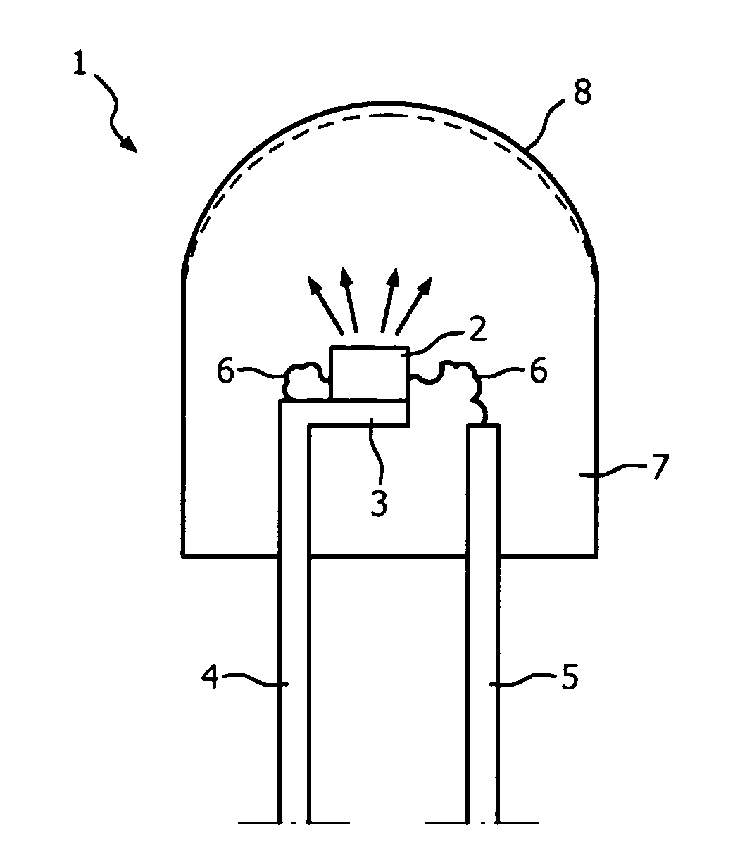
[0023]FIG. 1 illustrates in cross-section the lighting device 1 according to the present invention. Said lighting device 1 comprises a light source 2, which is embodied as a light emitting diode (LED). Although different types of LED can be used, it is preferred to apply a LED which is able to emit light having a wavelength of 500 nm or less. In the present device a LED of the GaInN type is used, which is able to emit light having a wavelength maximum of 450 nm. Said light source 2 is positioned on a part 3 of a power lead 4, which, together with a further power lead 5, arranges for electrical current that causes the LED to emit radiation. This radiation is indicated by the arrows that point away from the LED. The power leads 4, 5 include thin conducting wires 6 which are directly connected to the LED.

[0024]Light source 2 is encapsulated in a wavelength converting element 7, which has the shape of an optical lens. Converting element 7 is mainly composed of an organic polymer. A phos...

second embodiment

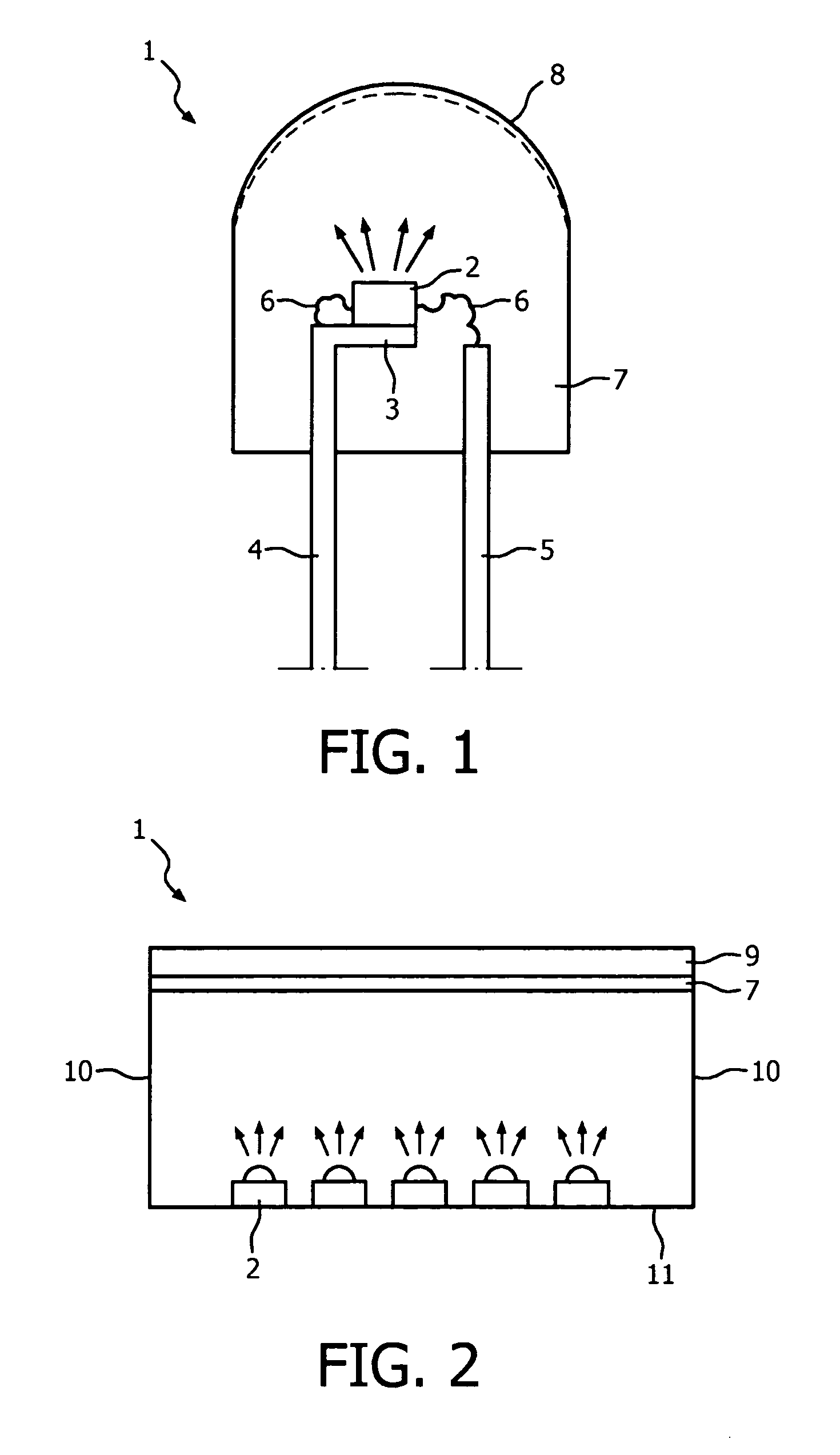
[0028]FIG. 2 illustrates in cross-section the lighting device 1 according to the present invention. Device 1 comprises a plurality of light sources 2 (again embodied as LEDs), of which only five are shown in cross-section. These LEDs may emit radiation of the same or of different wavelength. The direction of the radiation is indicated by small arrows. Upon activation of the light sources 2 via power leads and / or connection wires (not shown), the emitted light leaves the lighting device 1 via converting element 7, which is here formed as a plate. During passage of the plate-shaped converting element 7, (part of) the incident radiation is converted to radiation having a different wavelength. In the present device, said optical plate is attached to a substrate 9 which is transparent to the (converted) radiation. The side-walls 10 and the bottom-wall 11 are provided with reflecting means, so that a large portion of the generated radiation leaves the lighting device 1 via the wavelength ...


PUM


Abstract

The invention relates to a lighting (1) device comprising a light source (2) and a wavelength converting element (7), which comprises a phosphor compounded with a polymer. The phosphor contains a metal-ion activator which is excitable via a partially forbidden electronic transition. The phosphor and the polymer being chosen such that the difference in their refractive index is smaller than 0.1. Due to this choice, scattering in the wavelength converting element (7) remains at minimum. Interesting wavelength converting elements (7) are obtained when using phosphors comprising specific Mn(IV)-activated fluoride compounds and specific fluorine-containing polymers.

Description

FIELD OF THE INVENTION[0001]The invention relates to a lighting device comprising a light source arranged to emit light with a primary wavelength, and a wavelength converting element arranged to convert at least part-of the light with the primary wavelength into light with a secondary wavelength, the element comprising a phosphor with a metal-ion activator which is excitable via a partially forbidden electronic transition, said phosphor being compounded with a polymer. The invention also relates to a wavelength converting element suitable for use in such lighting device as well as to a method for the manufacture of a wavelength converting element.BACKGROUND OF THE INVENTION[0002]A lighting device of the type mentioned in the opening paragraph is known from the patent publication U.S. 2010 / 0096974-A1. This document describes a device comprising a LED having an encapsulant, which acts as a wavelength converting element. Said encapsulant is formed as a shell of a suitable plastic or gl...

Claims


Application Information

Patent Timeline
IPC IPC(8): H01L33/50C09K11/00G02F1/35F21V9/40
CPCC09K11/02C09K11/617H01L2224/48247H01L33/502H01L2933/0041C09K11/645C09K11/61F21V9/40H01L33/50
Inventor MEYER, JOERGWEILER, VOLKERSCHMIDT, PETER JOSEF
Owner KONINKLIJKE PHILIPS ELECTRONICS NV
Learn More