
Pressure vessel

Active Publication Date: 2012-10-11
HONDA MOTOR CO LTD
View PDF11 Cites 10 Cited by
  • Summary
  • Abstract
  • Description
  • Claims
  • Application Information

AI Technical Summary

Benefits of technology

[0014]According to the present invention, the detector intervenes not at the outer surface of the pressure vessel but between the liner and the reinforcing layer. By detecting the lifetime related value depending at least on one of the liner and the reinforcing layer from the physical quantity at the intervening region, it becomes possible to appropriately predict the lifetime of both the liner and the reinforcing layer. Further, it becomes possible to predict with high precision and immediately the lifetime of the pressure vessel that has piece-to-piece variation.
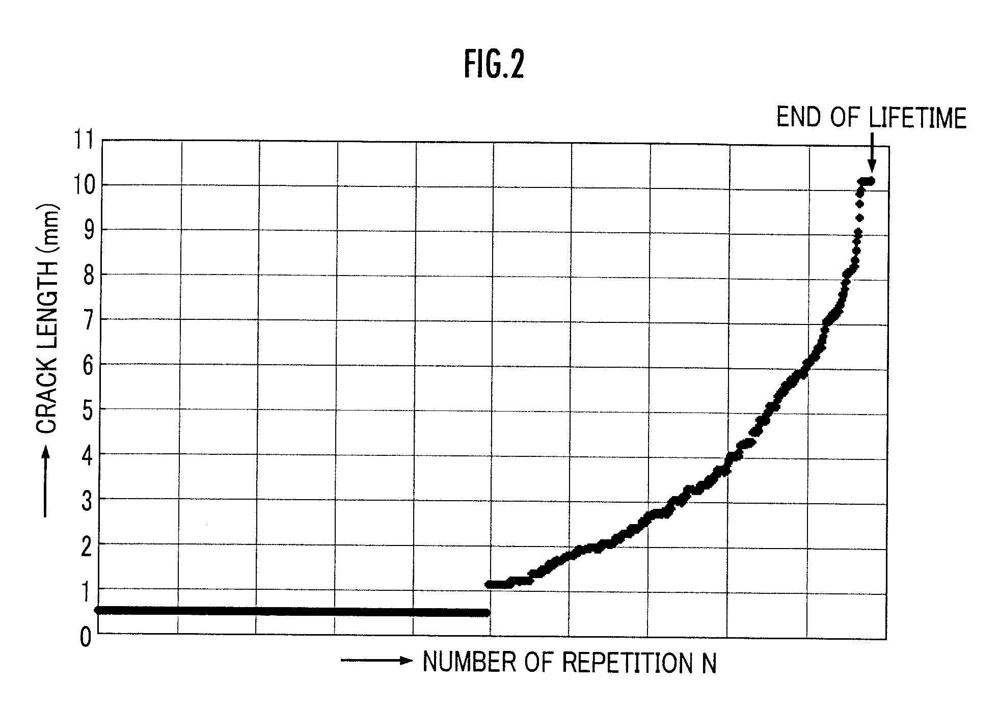
[0020]The length of the crack at the artificial imperfect structure increases, or the strain of the region of the artificial imperfect structure increases, as the pressure vessel is used longer. According to the preferred configuration mentioned above, it becomes possible to predict the lifetime of the pressure vessel with high precision and promptly, from the length of the crack or the change of the strain caused by the growth of the artificial imperfect structure accompanying the use of the pressure vessel.
[0022]According thereto, the imperfect structure in metal gradually grows together with the accumulation of the fatigue of the metal, whereas the imperfect structure in resin advances at once immediately before the end of the lifetime, so that the lifetime prediction from observing the imperfect structure is difficult. According to the preferred configuration mentioned above, in the pressure vessel equipped with the liner made of resin, the metal film member intervenes between the liner made of resin and the reinforcing layer. By providing the artificial imperfect structure to the metal film member, the lifetime of the pressure vessel may be smoothly predicted on the basis of the observation of the growth of the artificial imperfect structure, similar to the lifetime of the pressure vessel with the liner made of metal.
[0024]Load on the liner and the reinforcing layer may be smaller, as the amplitude fluctuation of the internal pressure of the pressure vessel becomes smaller. According to the preferred configuration mentioned above, the input-output amount of the pressurized fluid to and from the inside of the pressure vessel is controlled so as to restrain the fluctuation of the internal pressure as the pressure vessel approaches the end of the lifetime, so that the lifetime of the pressure vessel may be prolonged.

Problems solved by technology

The repetition of such pressure cycle becomes a cause of generation of cracks and growth thereof of the pressure vessel.
The growth of the crack affects a lifetime of the pressure vessel.
The conventional pressure vessels had large variation of the lifetime thereof, so that intensity more than necessary is imparted to the pressure vessels, leading to increased weight and increased price.
Of the conventional three lifetime predicting methods of the pressure vessel, the method (a) uniformly applies the examination result of the examination product to each pressure vessel, so that precision thereof decreases, and the methods (b) and (c) require extensive preparation for lifetime prediction and it is difficult to predict the same immediately.
Also, in the case where the monitoring device is applied for lifetime prediction of the pressure vessel, when the hole is processed on the outer surface of the pressure vessel, it will weaken the reinforcing layer so that the lifetime of the pressure vessel decreases at once.

Method used


Image

  • Pressure vessel
  • Pressure vessel
  • Pressure vessel

Examples


Embodiment Construction

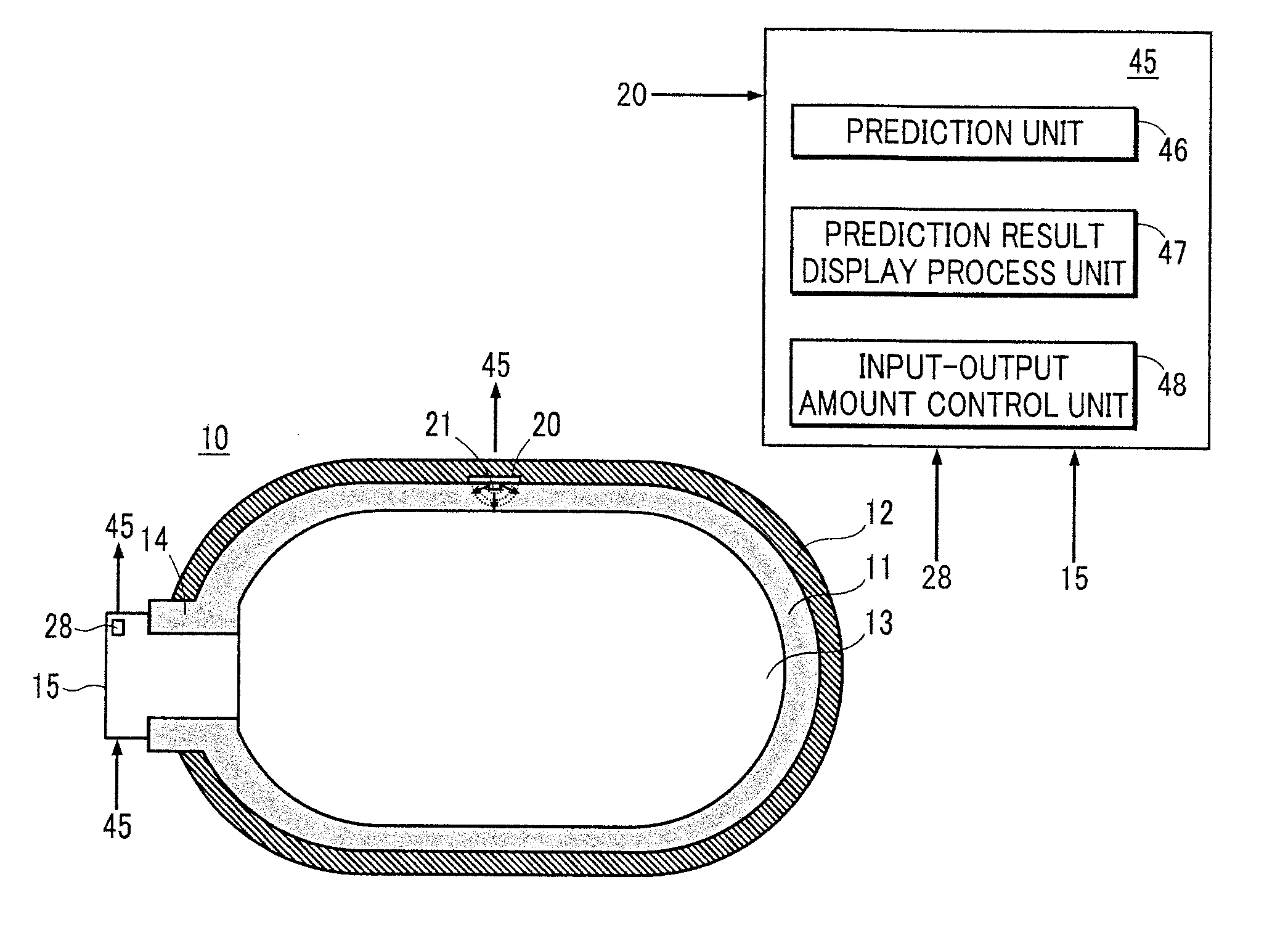
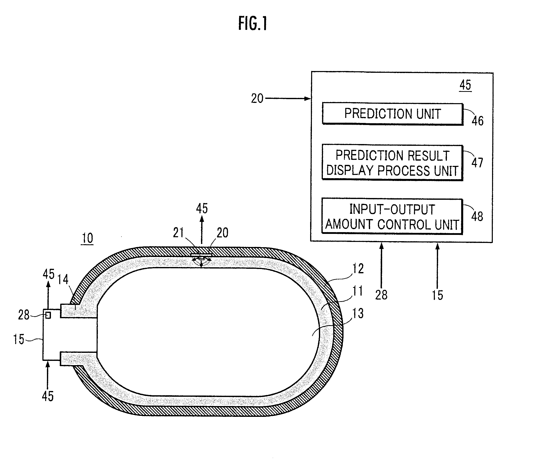
[0040]In FIG. 1, a hydrogen gas tank 10 corresponds to a pressure vessel of the present invention. The hydrogen gas tank 10 is mounted on a fuel cell vehicle (not shown). The hydrogen gas tank 10 is equipped with a liner 11 which defines a storage space 13 of a predetermined volume for storing a hydrogen gas as a fuel of a fuel cell at the inner surface side thereof, and a reinforcing layer 12 which surrounds the liner 11 by covering the outer surface of the liner 11.

[0041]The liner 11 is made of an aluminum alloy, and the reinforcing layer 12 is configured in a shape in which a resin-containing reinforced fiber is wrapped around an exterior surface of the liner 11. The resin-containing reinforced fiber is, for example a CFRP, which is a carbon fiber as a material fiber soaked with an epoxy resin as a matrix resin.

[0042]The hydrogen gas tank 10 is installed transversely. The liner 11 has a gateway 14 at one end portion of an axial direction thereof, and a valve device 15 is mounted ...


PUM

PropertyMeasurementUnit
Internal pressureaaaaaaaaaa
Stress optical coefficientaaaaaaaaaa

Abstract

A remaining lifetime of a pressure vessel mounted on a fuel cell vehicle or the like and comprises a liner at its inner side and a reinforcing layer at its outer side can be predicted with high precision and in short time. An artificial imperfect structure is formed at an outer surface of the liner in a size capable of being maintained by a weakest part of a hydrogen gas tank throughout the total period of use of the hydrogen gas tank. A detector is, for example, comprised of a crack gauge intervening between the liner and the reinforcing layer, and is fixed to the outer surface of the liner close to the artificial imperfect structure. A crack length increases accompanying the increase of a pressure cycle of an internal pressure caused by usage of the hydrogen gas tank. The detector increases a resistance value accompanying a crack growth.

Description

BACKGROUND OF THE INVENTIONField of the Invention[0001]The present invention relates to a pressure vessel which is mounted on a fuel cell vehicle and the like and which is equipped with a function for predicting a lifetime thereof.SUMMARY OF THE INVENTIONBackground Art[0002]A pressure vessel for storing a high-pressure gas as a fuel is mounted on a fuel cell vehicle or a compressed natural gas vehicle. The pressure vessel is a compound vessel equipped with a liner which defines a storage space of the high-pressure gas at the inner side thereof, and a reinforcing layer which surrounds the liner. Further, as a general material, an aluminum alloy or resin is adopted for the liner, and a CFRP (carbon fiber reinforced plastics) is adopted for the reinforcing layer.[0003]The pressure vessel repeats a pressure cycle in which the internal pressure rises by the filling of the high-pressure gas, and the internal pressure decreases accompanying the discharge to the fuel cell and the like. The ...

Claims


Application Information

Patent Timeline
IPC IPC(8): B65D1/40
CPCF17C13/02Y02E60/321F17C2201/056F17C2203/0619F17C2203/0646F17C2203/0663F17C2203/069F17C2221/012F17C2221/033F17C2223/0123F17C2223/036F17C2250/043F17C2250/0469F17C2250/0473F17C2250/0491F17C2250/0495F17C2260/042F17C2270/0168F17C2201/0109Y02E60/32
Inventor KANEZAKI, TOSHIHIKOMIYAGAWA, KAZUO
Owner HONDA MOTOR CO LTD
Learn More