
Non-Combustion Smoking Tool

a non-combustion smoking and tool technology, applied in the direction of ohmic-resistance heating, ohmic-resistance heating details, tobacco, etc., can solve the problems of smokers not being able to sufficiently inhale vaporized, difficult control of the heating temperature of the heater, short use time, etc., to achieve effective vaporization of cigarette smoke, reduce the size of components, and reduce power consumption

Inactive Publication Date: 2012-09-20
SHIMIZU KAZUHIKO
View PDF3 Cites 107 Cited by
  • Summary
  • Abstract
  • Description
  • Claims
  • Application Information

AI Technical Summary

Benefits of technology

[0012]FIG. 5 shows a structure of the heater having a novel structure adopted in the present invention. The heater having the novel structure is a heater comprising a linear part and a coil part, in which the linear part of the heater is inserted into a cigarette or a cigar, and is used only to preheat the leaves of the cigarette or the cigar. The coil part of the heater heats air around the coil part. (The heated air will be hereafter referred to as “hot air”.) The “hot air” passes through the cigarette or the cigar when a smoker inhales. Thus, it has an advantage that nicotine can be effectively vaporized from the cigarette or the cigar with the insertion.
[0013]Further, it has an advantage that when a current is applied to the heater having the novel structure adopted in the present invention, the surface temperature of the coil part of the heater rises by 70° C. or more than the linear part, allowing the surface temperature of the heater at the coil part to rise with a smaller current value than a heater having only a linear part, thus making it possible to use this tool with a battery or a rechargeable battery for a long time.
[0014]Further, the present invention has an advantage that the study of the control circuit allows reduction in power consumed by the circuit itself and reduction in size of components forming the circuit, making it possible to drive this tool with a battery or a rechargeable battery, and to reduce the size of the tool itself due to the reduction of the size of the circuit section.
[0015]Further, the present invention has an advantage that the power supplied to the heater can be controlled by the smoker, making it possible to smoke at a temperature desired by the smoker.
[0016]Further, the present invention has an advantage that, upon inhalation, the smoker can increase or decrease the power supplied to the heater from a power which the smoker predetermine.
[0017]Further, according to the “tool of the earlier application of the present application”, the tobacco leaves are continuously heated to cause a large amount of vaporization of water vapor from the tobacco leaves, which is condensed by the filter. This causes the problem that nicotine once generated by the heat is absorbed by the filter wetted with water, so that the smoker takes only a small amount of nicotine into mouth. However, the present invention has an advantage that the heating at the linear part is preheating, so that the vaporization of water vapor is reduced, preventing the filter from being wetted.

Problems solved by technology

However, when the “tool of the earlier application of the present application” was actually used, the following problems were found.Control of the heating temperature of a heater is difficult, and moreover requires some synchronization with inhalation by a smoker when actually smoking.Further, in order to make it possible to carry and use the tool anywhere, a battery or a rechargeable battery needs to be used as a power supply.
However, it requires addition of improvements to a driving circuit or a driving waveform for heating the heater, because otherwise the power consumption would be too high, causing a very short use time if a battery or a rechargeable battery is used.Further, when a filter cigarette is inserted into the tool for use, nicotine is vaporized by heating the tobacco leaves with the heater.
However, when inhaled through the filter, the nicotine once generated by the heat is absorbed by the filter, so that the smoker cannot sufficiently inhale the vaporized nicotine.Further, when a filter cigarette is inserted into the tool for use, water contained in the tobacco leaves is vaporized by heating the tobacco leaves with the heater, and is condensed by the filter, thereby wetting the filter and increasing the absorption of nicotine by the filter, so that the smoker cannot sufficiently inhale the vaporized nicotine.

Method used


Image

  • Non-Combustion Smoking Tool
  • Non-Combustion Smoking Tool
  • Non-Combustion Smoking Tool

Examples


Embodiment Construction

[0028]Hereinafter, detailed description will be made with reference to the drawings, giving a filter cigarette as an example of commercial cigarettes and cigars for the present invention. However, it is needless to say that the tool of the present invention can also be used for commercial plain cigarettes, cigars and the like, other than filter cigarettes.

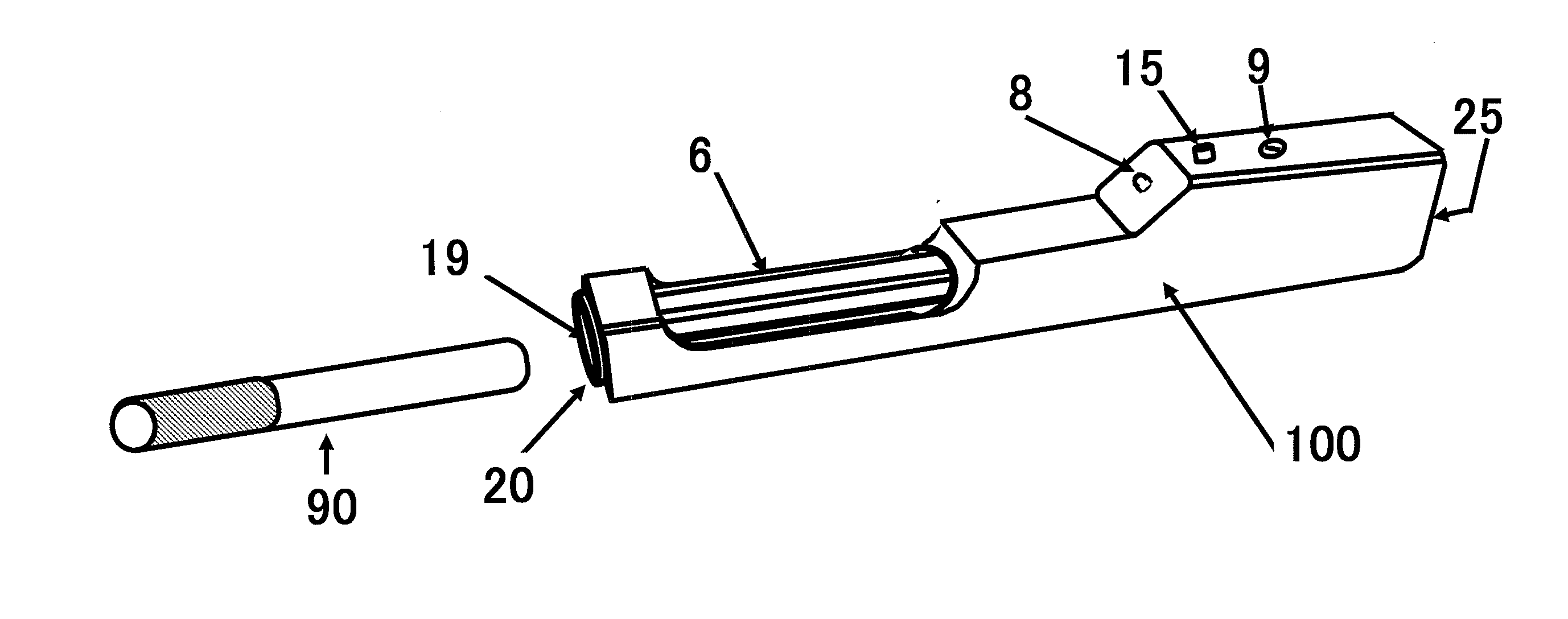
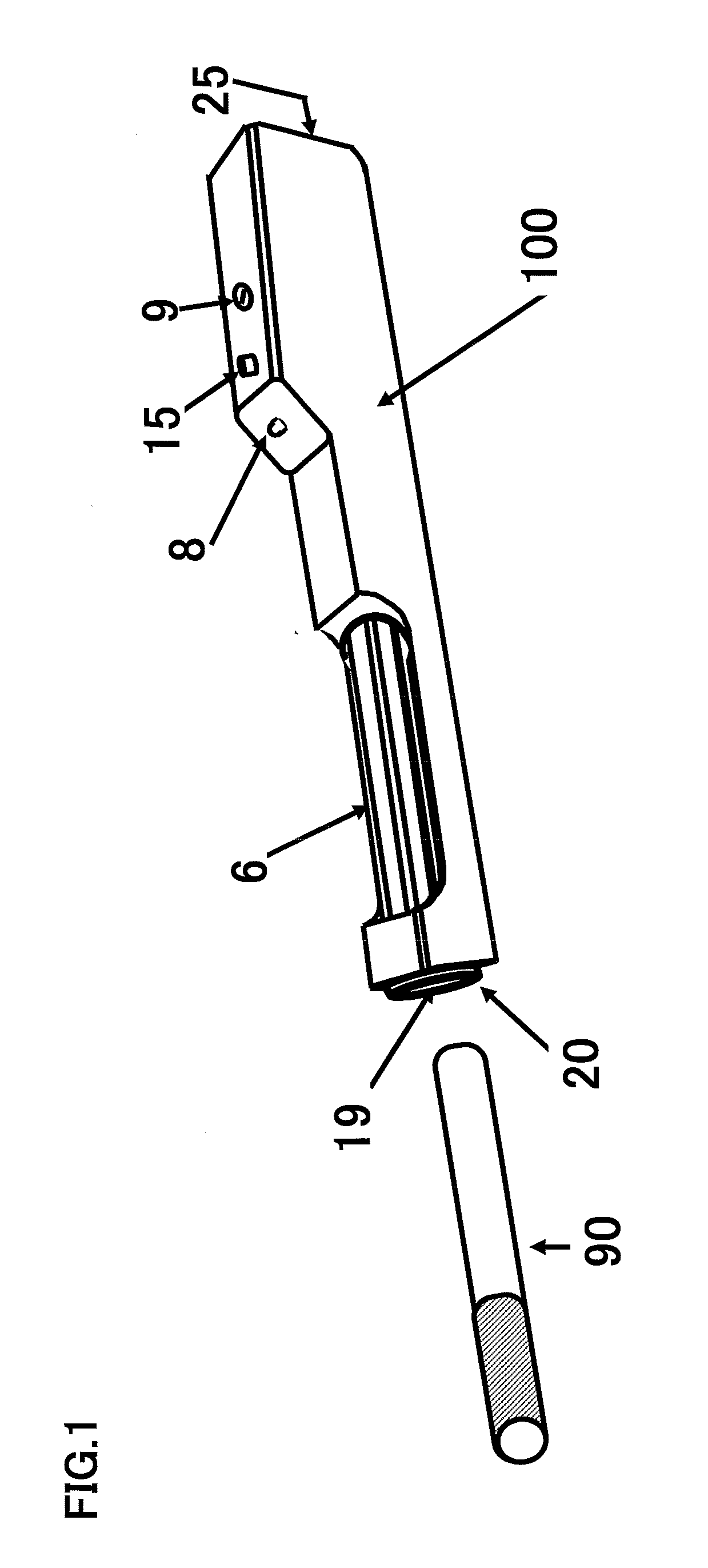
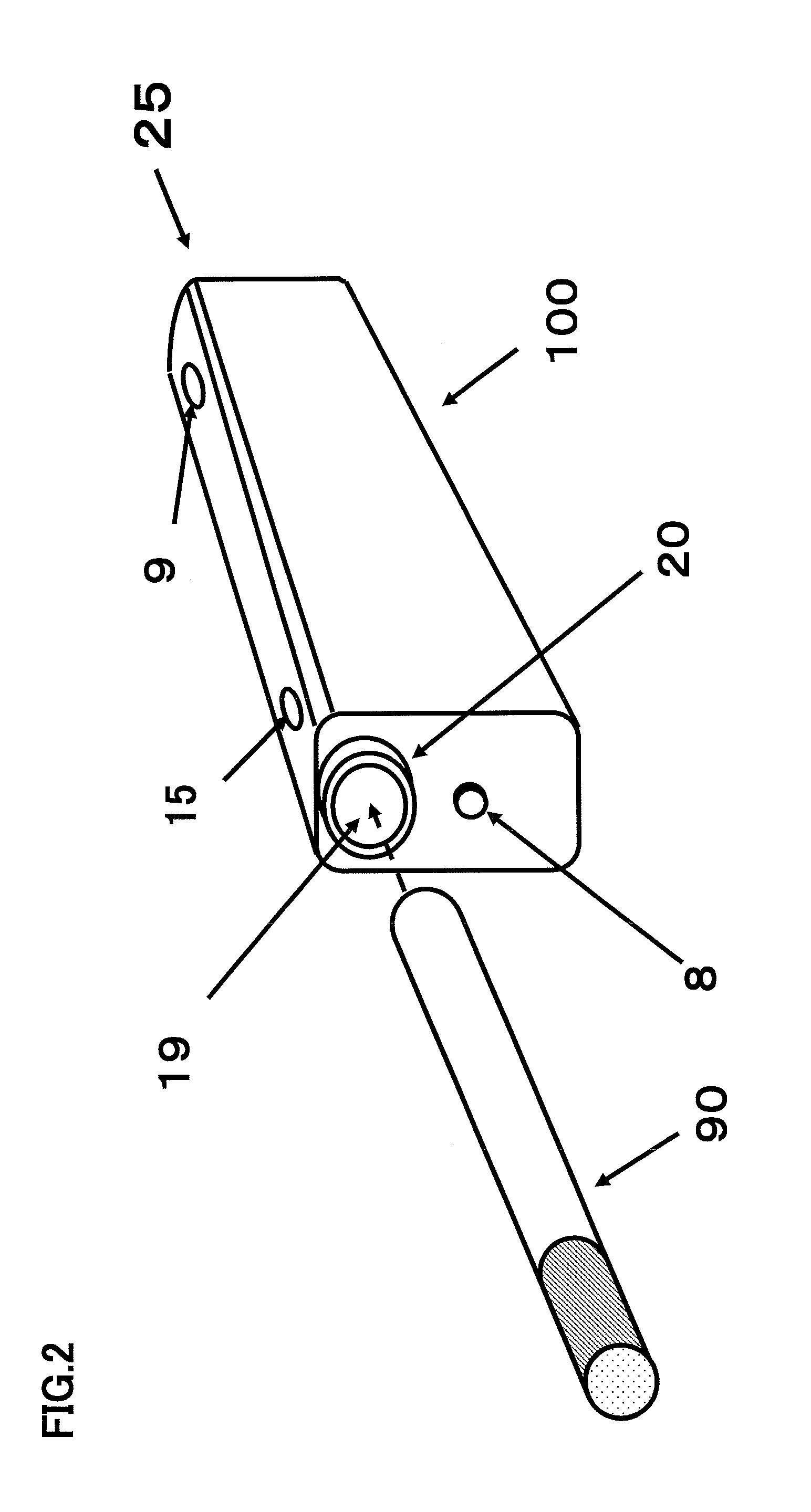
[0029]FIG. 1 shows appearance of an example of a tool according to the present invention. A tool 100 is composed of inner structural components comprising: a tobacco insertion opening 19 formed in a projection 20 for inserting a filter cigarette 90; an indicator 8 for indicating operation states; a Volume 9 for regulating power supplied to a heater 1; a Switch 15 for allowing a smoker to regulate power supplied to the heater 1 while smoking; a connector 10 (shown in FIG. 3) for receiving power from outside; an outside air inlet 25 (shown in FIG. 3); a thermal insulation material (glass pipe, ceramic pipe) 6; a component-embedded pr...


PUM


Abstract

A non-combustion smoking tool is usable with a commercial cigarette or cigar as it is, the tool vaporizes nicotine from the tobacco leaves and enables inhalation of the vaporized nicotine without burning the product. The non-combustion smoking tool has a heater to be used which includes a coil part and a linear part to be inserted into a commercial cigarette or cigar, wherein the linear part preheats the tobacco leaves, and the coil part heats air around the coil part so that, when a smoker inhales, the heated air around the coil part passes through the tobacco leaves so as to vaporize nicotine contained in the tobacco leaves and enable inhalation of the vaporized nicotine.

Description

TECHNICAL FIELD[0001]The present invention relates to an improvement over the non-combustion smoking tool of Japanese Patent Application No. 2009-049879 (having U.S. counterpart patent application Ser. No. 13 / 147,694) made by the present applicant (which will be referred to as “tool of the earlier application of the present application”), and the document of the earlier application is quoted in its entirety in the present application.BACKGROUND ART[0002]The “tool of the earlier application of the present application” has been proposed to improve various problems of a normal smoking method to light tobacco leaves for smoking, and a tool has been devised which, while using a generally commercial cigarette or cigar as it is, can vaporize nicotine from the tobacco leaves at a suitable temperature to enable inhalation without burning the tobacco leaves, making it possible to inhale nicotine.PRIOR ART DOCUMENT(S)Patent Document(s)[0003]Patent Document 1: Japanese Patent Application No. 20...

Claims


Application Information

Patent Timeline
IPC IPC(8): H05B3/02A24F40/20A24F40/46A24F40/50
CPCA24F47/008A24F13/00A24F40/46A24F40/50A24F40/20
Inventor SHIMIZU, KAZUHIKO
Owner SHIMIZU KAZUHIKO
Learn More