
Panoramic Imaging and Display System With Intelligent Driver's Viewer

a driver's viewer and panoramic imaging technology, applied in the field of image data processing, can solve the problems of putting the submarine in potentially hazardous situations, limited system resolution, and inability to achieve the highest achievable resolution, so as to improve safety and maneuverability.

Inactive Publication Date: 2012-09-13
KOLLMORGEN CORP
View PDF5 Cites 66 Cited by
  • Summary
  • Abstract
  • Description
  • Claims
  • Application Information

AI Technical Summary

Benefits of technology

[0008]Disclosed and claimed herein are systems for low-latency, high-resolution, continuous motion, staring panoramic video imaging. Also disclosed and claimed herein are systems that combine the advantages of such panoramic video imaging with advanced capabilities for intelligent and adaptive piloting and navigation. These systems have potential application to all types of military, commercial, and industrial vehicles that take advantage of remote camera systems where the driver may be situated in the vehicle or may be a remote pilot. In particular, these systems are well-suited to applications on military armored vehicles, remotely piloted vehicles that are deployable on land, sea, or in the air, while exploiting the best qualities of available camera imaging technologies to enhance safety and maneuverability.

Problems solved by technology

When operating passively in a contact dense environment, such manual contact identification can be time consuming and, in some instances, put the submarine in potentially hazardous situations.
Namely, the highest achievable resolution of the system is limited by the size of the focal plane / planes that can be physically utilized in the optical arrangement.
In addition, optical resolution is not uniform over the field of view.
This approach also suffers from mechanical challenges due to the need for a continuous transparent cylinder that must also provide a measure of structural rigidity.
This approach is computationally intensive, inefficient, cumbersome and may result in significant latency and processing overhead.
While this allows the camera line of sight to be redirected left or right so that more scene information may be gathered, it also poses the serious risk of distracting the driver from his main mission of piloting the vehicle.
In any case, standard DVE devices limit the total view and the amount of information available to the driver at any instant of time and may deprive him of valuable cues required to safely pilot his vehicle.

Method used


Image

  • Panoramic Imaging and Display System With Intelligent Driver's Viewer
  • Panoramic Imaging and Display System With Intelligent Driver's Viewer
  • Panoramic Imaging and Display System With Intelligent Driver's Viewer

Examples


Embodiment Construction

Overview of the Disclosure

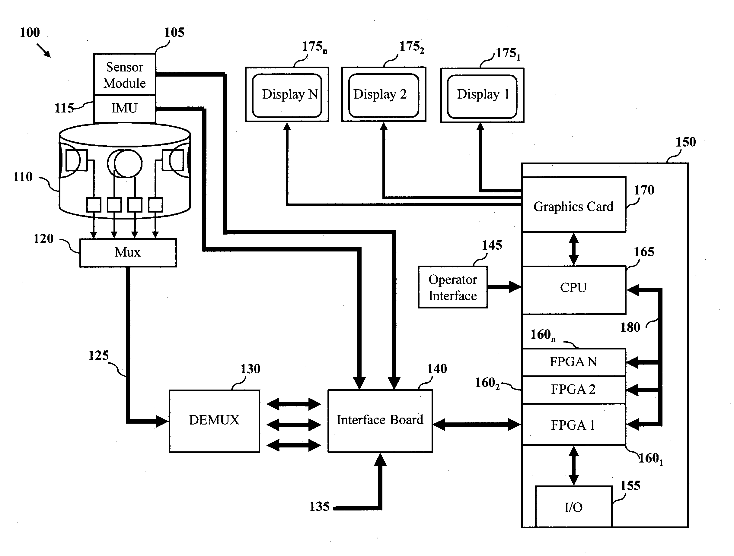
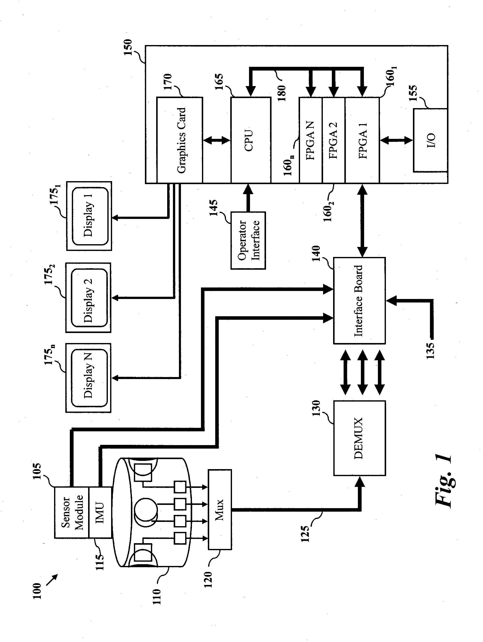
[0021]One aspect of the present invention relates to a panoramic imaging device. In one embodiment, an imaging device may be provided to include a plurality of high-resolution video cameras. The plurality of high-resolution cameras may be mounted in a housing or pod configured to arrange the video cameras in a one of a secure and adjustable fashion. Further, the video cameras may be configured to provide still images, motion images, a series of images and / or any type of imaging data in general.

[0022]As will be described in more detail below, the plurality of high-resolution video cameras may generate at least 500 kilopixel, per camera, at a minimum of 24 frames per second, near-real time video camera image signals representative of images in the field of view of the respective cameras. It should also be appreciated that other pixel values may be used. For example, in one embodiment, each camera may be configured to provide 1 megapixel image signals. A suppo...


PUM


Abstract

A system for low-latency, high-resolution, continuous motion, staring panoramic video imaging includes a plurality of high-resolution video cameras, each video camera generating about at least 500 kilopixel near-real time video. The cameras can be supported for positioning the plurality of cameras at predetermined angular locations to generate a full 360 degree field of view. The system can also include an image processor for processing video image signals in parallel and providing panoramic images. In one embodiment, the system can include a display to provide seamless panoramic images. In another embodiment, the panoramic imaging and display system incorporates an intelligent driver's viewer for use with vehicles which can intelligently and adaptively select and display a separate field of view in response to a variety of internal and external data inputs.

Description

CROSS-REFERENCE TO RELATED APPLICATIONS[0001]This application is a continuation-in-part of pending U.S. patent application Ser. No. 12 / 049,068, filed on Mar. 14, 2008, which claims the benefit of U.S. Provisional Patent Application Ser. No. 60 / 918,489, filed on Mar. 16, 2007, both of which are herein incorporated by reference in their entirety.FIELD OF THE INVENTION[0002]The present inventions relate to image data processing and more particularly to a system for the processing and display of imagery that combines panoramic viewing with an intelligent, adaptive display of real time images permitting simultaneous visual situational awareness and remote piloting and navigation under various and changing vehicle conditions.BACKGROUND[0003]The majority of the U.S. Navy's submarines still depend on the use of the age old periscope. At periscope depth, both the periscope and even the latest generation of non-penetrating photonics masts, which are installed on Virginia Class submarines for ...

Claims


Application Information

Patent Timeline
Patent Type & Authority Applications(United States)
IPC IPC(8): H04N5/225
CPCG06T3/4038H04N5/2624H04N5/23238H04N5/232H04N23/698
Inventor ROSE, MICHAEL KENNETHANDRYC, KEVIN ROBERTCHAMBERLAIN, JESSE DAVIDLAVALLEY, DANIEL LAWRENCE
Owner KOLLMORGEN CORP
Learn More