
Transmission device of a low-noise optical signal having a low-noise multi-wavelength light source, a transmission device of broadcast signals using a low-noise multi-wavelength light source, and an optical access network having the same

a transmission device and optical signal technology, applied in the direction of electromagnetic transmission, multi-band multiplexing, optical communication networks, etc., can solve the problems of low economic efficiency of wavelength division multiplexed optical communications network and optical access network, and does not have low-noise characteristic at other bands, etc., to enhance economic efficiency, enhance transmission characteristics, and improve the effect of efficiency

Inactive Publication Date: 2012-08-23
KOREA ADVANCED INST OF SCI & TECH
View PDF3 Cites 16 Cited by
  • Summary
  • Abstract
  • Description
  • Claims
  • Application Information

AI Technical Summary

Benefits of technology

[0030]1. It is possible to generate a plurality of lights (i.e., multi-wavelength lights) which are lasing at different wavelengths one another by one light source when using an LMLS according to the present invention, and enhance economic efficiency when applying such multi-wavelength lights into an optical communications network and an optical access network.
[0031]2. While an applicable technical field is narrow because a transmission speed is limited due to an increase of noise at a time of spectrum division in a prior art multi-wavelength light source, an LMLS according to the present invention improves dramatically the prior art problems and thus is capable of accomplishing a high speed, enhancing a transmission characteristic, and accommodating broadcast signals, etc., effectively.
[0032]3. Because an LMLS according to the present invention may be applicable not only to an optical access network but also to a metro network, the present invention is possible to contribute to lowering costs and enhancement of an optical transmitting system. Herein, the term “enhancement” means that an LMLS may be applicable to a long-distance transmission and thus it is possible to combine a metro network and an optical access network so that the number of intermediate central offices may be reduced.
[0014]Another object of the present invention is to amplify optical signals, which are wavelength division multiplexed, simultaneously, and reduce noises by embodying an optical amplifier using a gain medium for a low-noise multi-wavelength light source (LMLS) of the present invention.
[0034]5. In case of using an LMLS according to the present invention, it is possible to accommodate a broadcast signal transmission device into an optical communications network, which is difficult to be embodied up to date, and thus to embody an efficient optical access network capable of transmitting a multicast signal and a communications signal simultaneously.

Problems solved by technology

Therefore, it is required to use an expensive light source with high stability per a respective determined wavelength, and such a requirement becomes a most significant factor that lowers economic efficiency of a wavelength division multiplexed optical communications network and an optical access network.
However, because a noise characteristic of optical signals is influenced by a noise of injected incoherent broadband light in an optical transmission device which is wavelength-locked by incoherent broadband light according to prior art described above, there is a certain limitation relating to achieving a high-speed transmission (10 Gb / s or more per subscriber) of an optical communications network and it cannot suggest an appropriate alternative satisfying various requirements such as acceptability of broadcast signals of IP-TV in a WDM-PON, and subscriber-metro integrity, etc. FIG. 3 illustrates a view of a low-noise broadband light source embodied through a mutual injection of an F-P LD according to prior art.
However, a low-noise broadband light source embodied through a mutual injection of an F-P LD according to prior art described above has a disadvantage that it does not have a low-noise characteristic at other bands (especially, a high frequency band) except a specific frequency band.
As a result, even the low-noise broadband light source embodied through a mutual injection of an F-P LD has also a problem that it is not appropriate to be used in an optical communications network which requires an achievement of high-speed (10 Gb / s or more per subscriber), likewise in a WDM optical transmission device which is wavelength-locked by incoherent broadband light according to prior art described above.

Method used


Image

  • Transmission device of a low-noise optical signal having a low-noise multi-wavelength light source, a transmission device of broadcast signals using a low-noise multi-wavelength light source, and an optical access network having the same
  • Transmission device of a low-noise optical signal having a low-noise multi-wavelength light source, a transmission device of broadcast signals using a low-noise multi-wavelength light source, and an optical access network having the same
  • Transmission device of a low-noise optical signal having a low-noise multi-wavelength light source, a transmission device of broadcast signals using a low-noise multi-wavelength light source, and an optical access network having the same

Examples


first embodiment

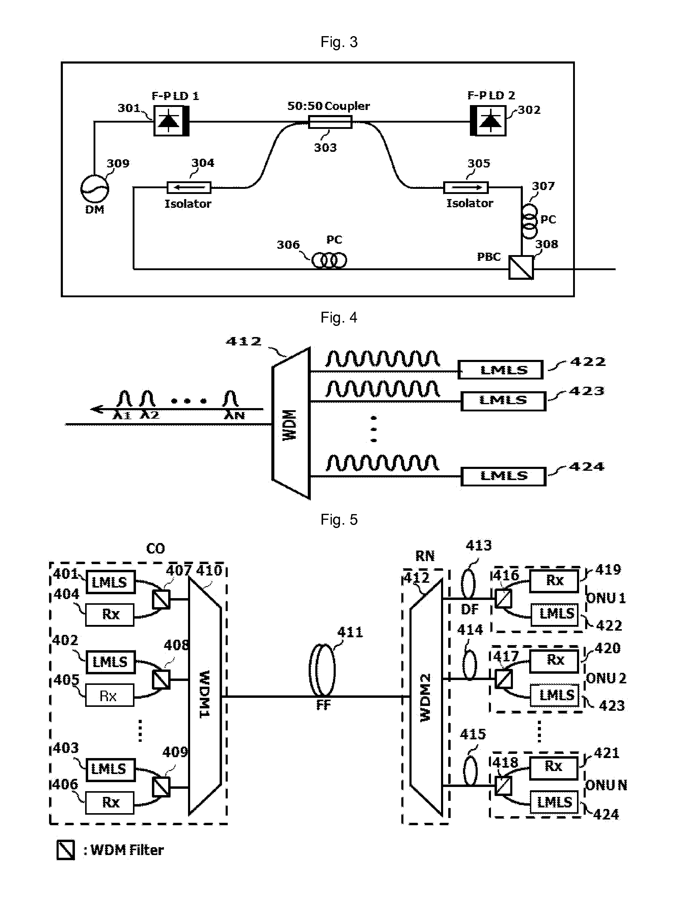
[0039]FIG. 4 illustrates a schematic view of a transmission device of a low-noise optical signal where a plurality of selected beams has a low-noise, respectively, even in case of selecting respectively different wavelengths from a plurality of plurality of lights beams being lasing at a multi-wavelength, by using a plurality of low-noise multi-wavelength light sources (LMLS) according to the present invention.

[0040]FIG. 5 illustrates a view of a wavelength division multiplexed optical access network having a transmission device of a low-noise optical signal according to a first embodiment of the present invention as illustrated in FIG. 4.

second embodiment

[0041]FIG. 6 illustrates a schematic view for explaining a transmission device of a low-noise optical signal where a plurality of spectrum-divided lights has a low-noise, respectively, even in case of spectrum-dividing one light being lasing at a multi-wavelength, by using a low-noise multi-wavelength light source (LMLS) according to the present invention.

[0042]FIG. 7 illustrates a schematic view of a transmission device of a low-noise optical signal where output lights outputted from a low-noise multi-wavelength light source (LMLS) from an LMLS according to a third embodiment of the present invention are spectrum-divided, while a plurality of spectrum-divided output lights is injected into a specific light source, respectively, of a plurality of optical transmitters (Tx).

[0043]FIG. 8 illustrates a schematic view of an embodiment of a wavelength division multiplexed optical access network having a transmission device of a low-noise optical signal according to a third embodiment of t...


PUM


Abstract

The present invention discloses a transmission device of a low-noise optical signal having a low-noise multi-wavelength light source, a transmission device of broadcast signals using a low-noise multi-wavelength light source, and an optical access network having the same.The present invention uses a low-noise multi-wavelength light source (LMLS) which has sufficiently low noises at respective wavelengths, while being lasing at a multi-wavelength. Noises at respective wavelengths are not increased, even though an output light of such an LMLS passes through a wavelength division multiplexer / demultiplexer (a tunable optical filter or an arrayed waveguide grating (AWG), etc.). When using an LMLS, it is possible to embody an optical access network capable of transmitting optical signals at a high-speed and simultaneously transmitting a multicast signal. Further, when embodying an optical amplifier by using a gain medium for an LMLS, it is possible to obtain gain at a broad band without cross-coupling.

Description

TECHNICAL FIELD[0001]The present invention relates to a transmission device of a low-noise optical signal having a low-noise multi-wavelength light source, a transmission device of broadcast signals using a low-noise multi-wavelength light source, and an optical access network having the same. More specifically, the present invention relates to a transmission device of a low-noise optical signal having a low-noise multi-wavelength light source, a transmission device of broadcast signals using a low-noise multi-wavelength light source, and an optical access network having the same where the noise such as mode partition noise, etc. is sufficiently low even in case of selecting respective wavelengths while a light source is lasing at a multi-wavelength.BACKGROUND ART[0002]Currently, a demand for the services of “fiber to the home” (FTTH) is constantly increasing, and a demand for a high transmission speed per subscriber is also increasing. Since the year of 1983, a required internet ba...

Claims


Application Information

Patent Timeline
Patent Type & Authority Applications(United States)
IPC IPC(8): H04J14/02H04B10/50
CPCH04B10/506H04B10/00H04B10/2581H04B10/50
Inventor LEE, CHANG-HEEKIM, JOON-YOUNGLEE, JONG-HOONMUN, SIL-GUMOON, JUNG-HYUNGLEE, HOON-KEUNOH, SANG-MINMUN, SANG-ROK
Owner KOREA ADVANCED INST OF SCI & TECH
Learn More